Toyota Sienna Service Manual: Diagnosis system
1. DESCRIPTION
- When troubleshooting OBD II (On-Board
Diagnostics) vehicles, an intelligent tester
(complying with SAE J1987) must be connected to
the DLC3 (Data Link Connector 3) of the vehicle.
Various data in the vehicle's ECM (Engine Control Module) can be then read.
- OBD II regulations require that the vehicle's onboard computer illuminates the MIL (Malfunction Indicator Lamp) on the instrument panel when the computer detects a malfunction in:

- The emission control systems and components
- The power train control components (which affect vehicle emissions)
- The computer itself In addition, the applicable DTCs (Diagnostic Trouble Codes) prescribed by SAE J2012 are recorded on 3 consecutive trips, the MIL turns off automatically but the DTCs remain recorded in the ECM memory.
- To check for DTCs, connect an intelligent tester to the DLC3. The tester displays DTCs, freeze frame data, and a variety of engine data. The DTCs and freeze frame data can be erased with the tester.
In order to enhance OBD function on vehicles and develop the Off-Board diagnosis system, CAN communication is introduced in this system (CAN: Controller Area Network). It minimizes a gap between technician skills and vehicle technology.
CAN is a network, which uses a pair of data transmission lines, spanning multiple computers and sensors. It allows a high speed communication between the systems and to simplify the wire harness connection.
Since this system is equipped with the CAN communication, connecting the CAN VIM (VIM: Vehicle Interface Module) with an intelligent tester is necessary to display any information from the ECM.
(Also the communication between the intelligent tester and the ECM uses CAN communication signal.) When confirming the DTCs and any data of the ECM, connect the CAN VIM between the DLC3 and the intelligent tester.
2. NORMAL MODE AND CHECK MODE
- The diagnosis system operates in normal mode during normal vehicle use. In normal mode, 2 trip detection logic is used to ensure accurate detection of malfunctions. Check mode is also available as an option for technicians. In check mode, 1 trip detection logic is used for simulating malfunction symptoms and increasing the system's ability to detect malfunctions, including intermittent problems (intelligent tester only).
3. 2 TRIP DETECTION LOGIC
- When a malfunction is first detected, the malfunction is temporarily stored in the ECM memory (1st trip). If the same malfunction is detected during the next subsequent drive cycle, the MIL is illuminated (2nd trip).
4. FREEZE FRAME DATA
- The ECM records vehicle and driving condition information as freeze frame data the moment a DTC is stored. When troubleshooting, freeze frame data can be helpful in determining whether the vehicle was running or stopped, whether the engine was warmed up or not, whether the air-fuel ratio was lean or rich, as well as other data recorded at the time of a malfunction.
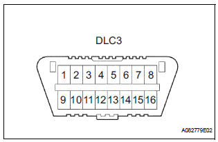
5. DLC3 (Data Link Connector 3)
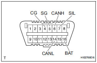
- The vehicle's ECM uses ISO 15765-4 for communication protocol. The terminal arrangement of the DLC3 complies with SAE J1962 and matches the ISO 15765-4 format.
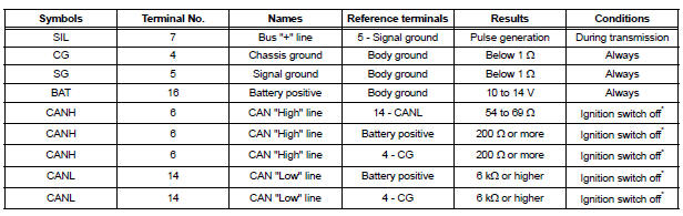
NOTICE: *: Before measuring the resistance, leave the vehicle as is for at least 1 minute and do not operate the ignition switch, any other switches or the doors.
HINT: The DLC3 is the interface prepared for reading various data from the vehicle's ECM. After connecting the cable of an intelligent tester, turn the ignition switch to the ON position and turn the tester ON.
- If a communication failure message is displayed on the tester screen (on the tester: UNABLE TO CONNECT TO VEHICLE), a problem exists in either the vehicle or tester. In order to identify the location of the problem, connect the tester to another vehicle.
- If communication is normal: Inspect the DLC3 on the original vehicle.
- If communication is impossible: The problem is probably in the tester itself. Consult the Service Department listed in the instruction manual.
6. BATTERY VOLTAGE
Battery Voltage: 11 to 14 V
If the voltage is below 11 V, recharge the battery before proceeding to the next step.
7. MIL (Malfunction Indicator Lamp)
- The MIL is illuminated when the ignition switch is first turned to the ON position (the engine is not running).
- The MIL should turn off when the engine is started.
If the MIL remains illuminated, the diagnosis system has detected a malfunction or abnormality in the system.
HINT: If the MIL is not illuminated when the ignition switch is first turned to the ON position, check the MIL circuit
 Terminals of ECM
1. SFI SYSTEM
HINT:
The standard normal voltage between each pair of the
ECM terminals is shown in the table below. The
appropriate conditions for checking each pair of the
terminals are also i ...
 DTC check / clear
NOTICE:
All the stored DTCs and freeze frame data are erased if:
the ECM is changed from normal mode to check mode
or vice versa; or 2) the ignition switch is turned from ON
to ACC or o ...
Other materials:
Removal
NOTICE:
Do not adjust the brake booster push rod.
Do not change the combination of the diameter
converting unit and brake.
1. REMOVE FRONT WHEEL
2. DRAIN BRAKE FLUID
NOTICE:
Wash the brake fluid off immediately if it attaches to
any painted surfaces.
3. SEPARATE BATTERY NEGATIVE TERM ...
Inspection
1. INSPECT FRONT SEAT INNER BELT ASSEMBLY RH
Release the seat belt (Buckle switch is ON).
Check the resistance between the terminals.
Standard
If the result is not as specified, replace the inner belt
assembly.
Inspect the buckle switch.
Fasten ...
Diagnostic trouble code chart
HINT:
The parameters listed in the chart may not confirm exactly to
those read during the DTC check due to the type of
instrument or other factors.
If a trouble code is displayed during the DTC check in the
check mode, check the circuit for the code listed in the table
below. For details of ...
