Toyota Sienna Service Manual: Removal
1. DISCONNECT CABLE FROM NEGATIVE BATTERY TERMINAL
2. REMOVE STEERING WHEEL NO. 2 LOWER COVER
3. REMOVE STEERING WHEEL NO. 3 LOWER COVER
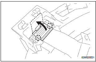
4. REMOVE HONE BUTTON ASSEMBLY
5. REMOVE STEERING PAD SWITCH LH
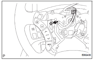
- Disconnect the connector.
- Disconnect the connector of cruise control main switch.
- Remove the screw.
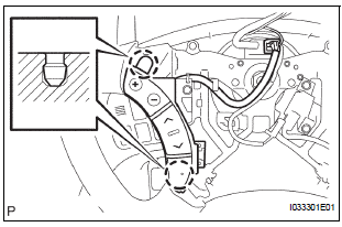
- w/o Laser radar cruise control:
- Release the 2 pin fittings and remove the steering pad switch LH.
- w/ Laser radar cruise control:
- Remove the clamp.
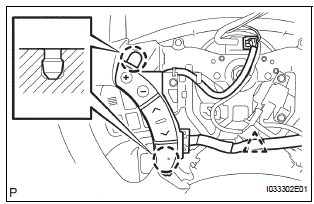
- w/ Laser radar cruise control:
- Release the 2 pin fittings and release the steering pad switch LH from steering wheel.
- w/ Laser radar cruise control:
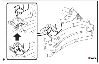
- Release the tab of steering pad switch cable from steering pad switch LH as shown in the illustration.
- w/ Laser radar cruise control:
- Disengage the 2 claws as shown in the illustration and open the latch on the top of the connector.
- w/ Laser radar cruise control:
- Pull out the connector while pinching the latch with fingers and disconnect the steering pad switch cable from the steering pad switch LH.
 Steering pad switch
COMPONENTS
...
 Inspection
1. INSPECT STEERING PAD SWITCH LH (w/o
Navigation System)
Measure the resistance according to the values in
the table below.
Standard resistan
If the result is not as specifie ...
Other materials:
Child restraint systems with a top tether strap (second seat)
Secure the child restraint system
using the seat belt or
LATCH anchors, and adjust the
head restraint to the uppermost
position.
*: Ottoman seat only
Latch the hook onto the anchor
bracket and tighten the top
tether strap.
Make sure the top tether strap is
secure ...
Display Signal Circuit between Television Display Assembly and Radio
and Navigation Assembly
DESCRIPTION
This circuit sends a DVD image signal from the television display assembly to
the radio and navigation
assembly.
WIRING DIAGRAM
INSPECTION PROCEDURE
1 CHECK HARNESS AND CONNECTOR (RADIO AND NAVIGATION ASSEMBLY - TELEVISION
DISPLAY ASSEMBLY)
Disconnect the radio and n ...
Vehicle Speed Signal Circuit between Multi-display and Combination
Meter
DESCRIPTION
This circuit is necessary for the ASL (Auto Sound Leveliser) built into the
radio receiver.
Speed signals are received from the combination meter and used for the ASL.
The ASL function automatically adjusts the sound data in order to enable hearing
the clear audio sound
even ...
