Toyota Sienna Service Manual: Power Slide Door LH does not Operate When Using Inside / Outside Handle
DESCRIPTION
- The inside / outside handles have the ability to control operation of the power slide door. Pulling either handle transmits a request signal to the power slide door ECU LH, which then commands the power slide door control motor and clutch to open / close the power slide door.
- The slide door lock remote control assembly has the handle operation detect switch for detection of switch operation and also the child protection detect switch for the child lock function that disables the power slide door control switch LH function while the child lock is ON.
- If there is a malfunction detected in these 2 detection switches or the wire harness, replace the slide door lock remote control assembly LH.
WIRING DIAGRAM
INSPECTION PROCEDURE
1 OPERATION CHECK
- If the power slide door does not operate when trying to open it, proceed to A.
- If the power slide door does not operate when trying to close it, proceed to B.
2 CHECK SLIDE DOOR CLOSER SYSTEM
- Check if the slide door closer system operates.
3 READ VALUE OF INTELLIGENT TESTER
- Using the intelligent tester, check the DATA LIST for proper functioning of the handle operation detect switch.
OK (Power slide door ECU LH):
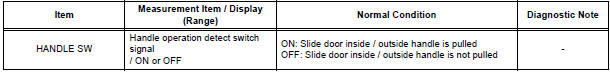
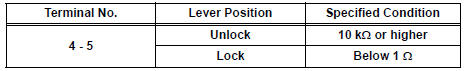
4 INSPECT SLIDE DOOR LOCK REMOTE CONTROL SUB-ASSEMBLY LH (HANDLE OPERATION DETECT SWITCH)
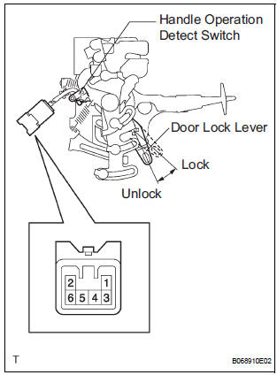
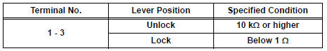
- Inspect the resistance of the switch.
Resistance
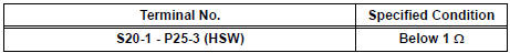
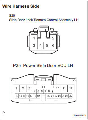
5 CHECK WIRE HARNESS (SLIDE DOOR LOCK REMOTE CONTROL - POWER SLIDE DOOR ECU LH)
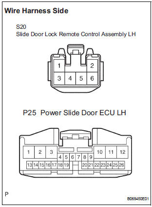
- Disconnect the S20 remote control and P25 ECU connectors.
- Check the resistance between the wire harness side connectors.
Resistance (Check for open circuit)
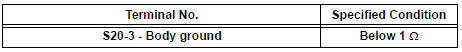
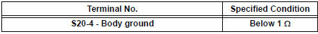
- Check the resistance between the S20 remote control connector and body ground.
Resistance (Check for open circuit)
REPLACE POWER SLIDE DOOR ECU LH
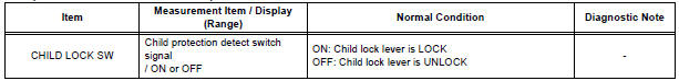
6 READ VALUE OF INTELLIGENT TESTER
- Using the intelligent tester, check the DATA LIST for proper functioning of the child protection detect switch.
OK (Power slide door ECU LH):
7 INSPECT SLIDE DOOR LOCK REMOTE CONTROL SUB-ASSEMBLY LH (CHILD PROTECTION DETECT SWITCH)
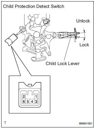
- Inspect the resistance of the switch.
Resistance
8 CHECK WIRE HARNESS (SLIDE DOOR LOCK REMOTE CONTROL - POWER SLIDE DOOR ECU LH)
- Disconnect the S20 switch and P25 ECU connectors.
- Check the resistance between the wire harness side connectors.
Resistance (Check for open circuit)

- Check the resistance between the S20 switch connector and body ground.
Resistance (Check for open circuit)
REPLACE POWER SLIDE DOOR ECU LH
 Inspection procedure
1 BASIC INSPECTION
Conditions necessary for the power slide door to open:
Power slide door main switch is in the ON position
(switch free: orange paint on the top of the switch
appears). ...
 Power Slide Door RH does not Operate When Using Inside / Outside
Handle
Power Slide Door RH does not Operate When Using Inside / Outside
Handle
DESCRIPTION
The inside / outside handles have the ability to control operation
of the power slide door. Pulling either
handle transmits a request signal to the power slide door ECU RH, ...
Other materials:
Oxygen Sensor Heater Control Circuit
HINT:
Sensor 2 refers to the sensor mounted behind the Three-Way Catalytic
Converter (TWC) and located
furthest from the engine assembly.
DESCRIPTION
Refer to DTC P0136 (See page ES-160).
HINT:
When any of these DTCs are set, the ECM enters fail-safe mode. The ECM turns
off the Heated ...
Stop light switch
ON-VEHICLE INSPECTION
1. STOP LIGHT SWITCH ASSEMBLY
Check the resistance between the terminals at each
switch position as shown ion the chart.
Resistance
...
System description
1. DESCRIPTION OF OCCUPANT CLASSIFICATION SYSTEM
GENERAL DESCRIPTION.
In the occupant classification system, the
occupant classification ECU calculates the
weight of the occupant based on a signal from
the occupant classification sensors. This system
recognizes the occu ...
