Toyota Sienna Service Manual: Diagnosis system
1. CHECK DLC3
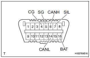
- The ECU uses ISO 15765-4 for communication.
The terminal arrangement of the DLC3 complies with SAE J1962 and matches the ISO 15765-4 format.
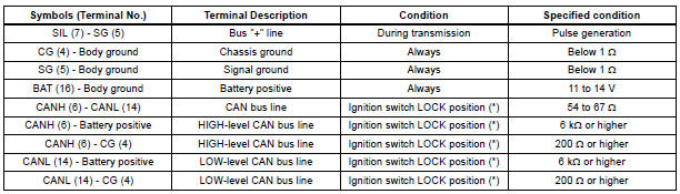
NOTICE: *: Before measuring the resistance, leave the vehicle as is for at least 1 minute and do not operate the ignition switch, any other switches, or the doors.
If the result is not as specified, the DLC3 may have a malfunction. Repair or replace the harness and connector.
HINT: If the display shows a communication error message when connecting the cable of the intelligent tester to the DLC3, turning the ignition switch to the ON position and operating the intelligent tester, there is a problem on the vehicle side or tool side.
- If communication is normal when the tool is connected to another vehicle, inspect the DLC3 on the original vehicle.
- If communication is still not possible when the tool is connected to another vehicle, the problem is probably in the tool itself. Consult the Service Department listed in the tool's instruction manual.
2. SYMPTOM SIMULATION
HINT:
The most difficult case in troubleshooting is when no symptoms occur. In such cases, a thorough customer problem analysis must be carried out. Then the same or similar conditions and environment in which the problem occurred in the customer's vehicle should be simulated.
No matter how experienced or skilled a technician may be, if he proceeds to troubleshoot without confirming the problem symptoms, he will likely overlook something important and make a wrong guess at some points in the repair operation.
This leads to a standstill in troubleshooting.
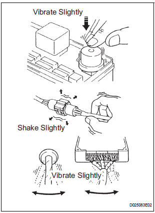
- Vibration method: When vibration seems to be the major cause.
HINT: Perform the simulation method only during the primary check period (for approximately 6 seconds after the ignition switch is turned to the ON position).
- Slightly vibrate the part of the sensor considered to be the problem with your fingers and check whether the malfunction occurs.
HINT: Shaking the relays too strongly may result in open relays.
- Slightly shake the connector vertically and horizontally.
- Slightly shake the wire harness vertically and
horizontally.
The connector joint and fulcrum of the vibration are the major areas to be checked thoroughly.
3. FUNCTION OF SRS WARNING LIGHT
- Primary check.
- Turn the ignition switch to the LOCK position.
After 2 seconds or more, turn the ignition switch to the ON position. The SRS warning light comes on for approximately 6 seconds and the diagnosis of the SRS airbag system (including the seat belt pretensioner and front passenger occupant classification system) is performed.
HINT: If trouble is detected during the primary check, the SRS warning light remains on even after the primary check period (for approximately 6 seconds) has elapsed.
- Constant check.
- After the primary check, the center airbag sensor assembly constantly monitors the airbag system for trouble.
HINT: If trouble is detected during the constant check, the center airbag sensor assembly functions as follows:
- The SRS warning light comes on.
- The SRS warning light goes off, and then comes on. This blinking pattern indicates a source voltage drop. The SRS warning light goes off 10 seconds after the source voltage returns to normal.
- Review.
- When the airbag system is normal: The SRS warning light comes on only for the primary check period (for approximately 6 seconds after the ignition switch is turned to the ON position).
- When the airbag system has trouble:
- The SRS warning light remains on even after the primary check period has elapsed.
- The SRS warning light goes off after the primary check, but comes on again during the constant check.
- The SRS warning light does not come on when turning the Ignition switch from the LOCK to the ON position.
HINT: The center airbag sensor assembly keeps the SRS warning light on if the airbag has been deployed.
4. SRS WARNING LIGHT CHECK
- Turn the ignition switch to the ON position, and check that the SRS warning light comes on for approximately 6 seconds (primary check).
- Check that the SRS warning light goes off approximately 6 seconds after the ignition switch is turned to the ON position (constant check).
HINT: When any of the following symptoms occur, refer to the "Problem Symptoms Table".
- The SRS warning light comes on occasionally, after the primary check period has elapsed.
- The SRS warning light comes on, but a DTC is not output.
- When the ignition switch is turned to ON position, the SRS warning light does not come on.
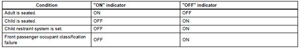
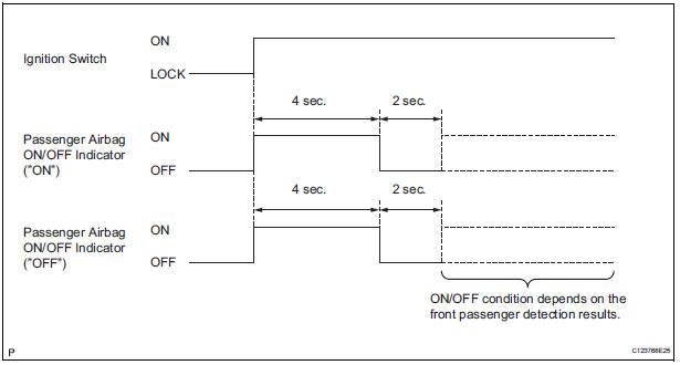
5. FUNCTION OF PASSENGER AIRBAG ON/OFF INDICATOR
- Initial check
- Turn the ignition switch to the ON position.
- The passenger airbag ON/OFF indicator comes on for approximately 4 seconds, then goes off for approximately 2 seconds.
- Approximately 6 seconds after the ignition switch is turned to the ON position, the passenger airbag ON/OFF indicator will be ON/ OFF depending on the conditions listed below.

HINT:
- The passenger airbag ON/OFF indicator is based on the timing chart below in order to check the indicator light circuit.
- When the front passenger occupant
classification system has trouble, both the
SRS warning light and the passenger airbag
ON/OFF indicator come on. In this case,
check the DTCs in the Airbag System first.
Then troubleshoot the Occupant Classification System if DTC B1150/23 is detected, and troubleshoot the passenger airbag ON/OFF indicator if DTC B1152/28 is detected.
6. PASSENGER AIRBAG ON/OFF INDICATOR CHECK
- Turn the ignition switch to the ON position.
- Check that the passenger airbag ON/OFF indicator ("ON" and "OFF") comes on for approximately 4 seconds, then goes off for approximately 2 seconds.
HINT: Refer to the table in the previous step regarding the passenger airbag ON/ OFF indicator when the ignition switch is turned to the ON position and approximately 6 seconds pass.
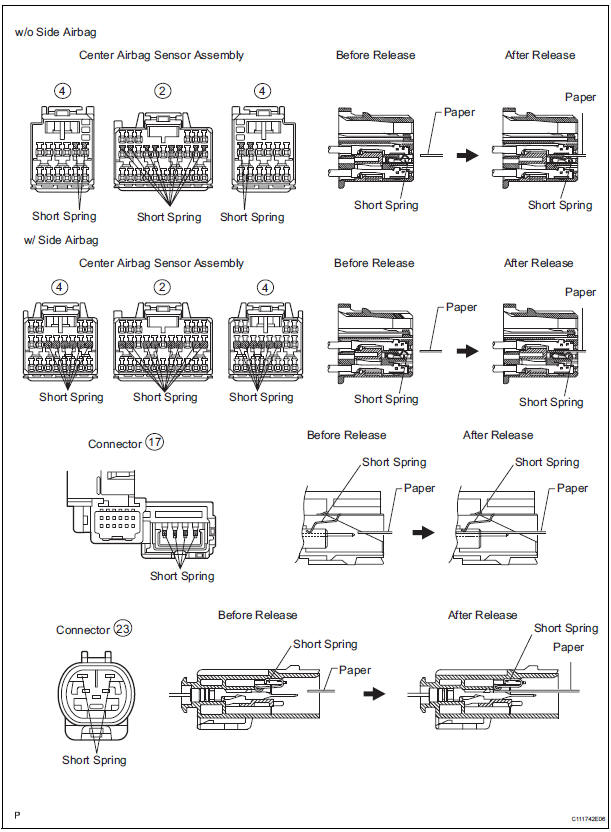
7. ACTIVATION PREVENTION MECHANISM
- FUNCTION OF ACTIVATION PREVENTION MECHANISM
- An activation prevention mechanism is built into the connector (on the center airbag sensor assembly side) of the airbag system squib circuit to prevent accidental airbag activation.
- This mechanism closes the circuit when the connector is disconnected by bringing the short spring into contact with the terminals and shutting off external electricity to prevent accidental airbag activation.
- RELEASE METHOD OF ACTIVATION PREVENTION MECHANISM
- To release the activation prevention mechanism, insert a piece of paper with the same thickness as the male terminal (approximately 0.5 mm (0.020 in.)) between the terminals and the short spring to break the connection.
- Refer to the illustrations on the next 2 pages for connectors used in the activation prevention mechanism and its release method.
CAUTION: Never release the activation prevention mechanism on the squib connector even when inspecting with the squib disconnected.
NOTICE:
- Do not release the activation prevention mechanism unless specially directed by the troubleshooting procedure.
- To prevent the terminal and the short spring from becoming damaged, always use a piece of paper with the same thickness as the male terminal.
 Terminals of ECU
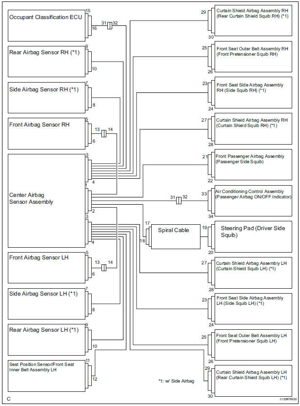
1. CENTER AIRBAG SENSOR ASSEMBLY (w/ Side
Airbag)
2. CENTER AIRBAG SENSOR ASSEMBLY (w/o Side
Airbag)
...
 DTC check / clear
1. DTC CHECK (USING SST CHECK WIRE)
Check the DTCs (Present trouble code).
Turn the ignition switch ON, and wait for
approximately 60 seconds.
Using SST, connect term ...
Other materials:
Problem symptoms table
HINT:
Use the table below to help determine the cause of the
problem symptom. The potential causes of the symptoms are
listed in order of probability in the "Suspected Area" column
of the table. Check each symptom by checking the suspected
areas in the order they are listed. Replace p ...
Installation
1. INSTALL STABILIZER BAR FRONT
2. INSTALL FRONT STABILIZER BAR BUSH NO.1
(a) Install the front stabilizer bar bush No. 1.
HINT:
Install the bushing to the outer side of the bushing
stopper on the stabilizer bar as shown in the
illustration.
4. INSTALL RACK & PINION POWER STEERING GEA ...
If the battery is
discharged
The following procedures may be used to start the engine if the
vehicle’s battery is discharged.
You can call your Toyota dealer or qualified repair shop.
If you have a set of jumper (or booster) cables and a second vehicle
with a 12-volt battery, you can jump start your vehicle by following ...
