Toyota Sienna Service Manual: Diagnosis system
1. CHECK DLC3
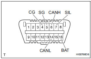
- The vehicle's ECU uses ISO 15765-4 for communication protocol. The terminal arrangement of the DLC3 complies with SAE J1962 and matches the ISO 15765-4 format.
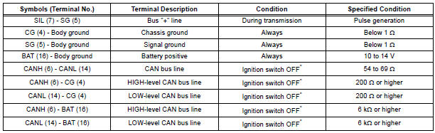
NOTICE: *: Before measuring the resistance, leave the vehicle as is for at least 1 minute and do not operate the ignition switch, any other switches or the doors.
If the result is not as specified, the DLC3 may have a malfunction. Repair or replace the harness and connector.
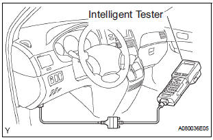
- Connect the cable of the intelligent tester to the DLC3, turn the ignition switch to the ON position and attempt to use the intelligent tester. If the screen displays a communication error message, a problem exists in the vehicle side of the tester side.
HINT:
- If communication is normal when the tool is connected to another vehicle, inspect the DLC3 on the original vehicle.
- If communication is still impossible when the tool is connected to another vehicle, the problem is probably in the tool itself. Consult the Service Department listed in the tool's instruction manual
 Terminals of ECU
1. CHECK POWER SLIDE DOOR ECU LH (WITH
POWER SLIDE DOOR)
Disconnect the P25 and P26 ECU connectors, and
check the voltage and resistance of each terminal of
the wire harness side connecto ...
 DTC check / clear
1. CHECK DTC (USING INTELLIGENT TESTER)
Checking DTCs.
Connect the intelligent tester to the DLC3.
Turn the ignition switch ON.
Read DTCs by following the prompts o ...
Other materials:
Disposal
1. DISPOSE OF SHOCK ABSORBER ASSEMBLY REAR LH
(a) Fully extend the shock absorber rod.
(b) Using a drill, make a hole in the cylinder as shown in
the illustration to discharge the gas inside the
cylinder.
CAUTION:
When drilling, since the fragments may fly
out, work careful ...
DTC check / clear
1. DTC CHECK
HINT:
When DTC B1150/23 is detected as a result of
troubleshooting for "Airbag System", perform
troubleshooting for the Occupant Classification System.
Check the DTCs.
Connect the intelligent tester to the DLC3
Turn the ignition switch to ...
Removal
1. REMOVE FRONT SEAT INNER BELT ASSEMBLY
HINT:
Refer to the instructions for disassembly of the front
seat assembly (for flat type).
Refer to the instructions for disassembly of the front
seat assembly (for manual seat).
Refer to the instructions for disassembly of the ...
