Toyota Sienna Service Manual: Terminals of ECU
1. CHECK POWER SLIDE DOOR ECU LH (WITH POWER SLIDE DOOR)
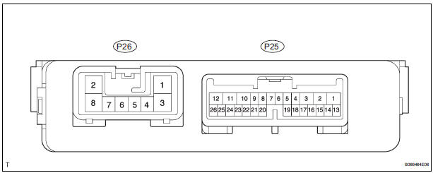
- Disconnect the P25 and P26 ECU connectors, and check the voltage and resistance of each terminal of the wire harness side connectors.
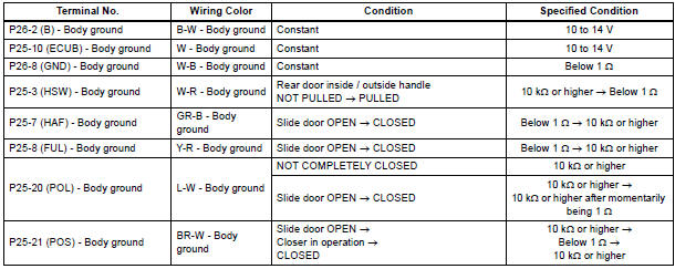
If the result is not as specified, there may be a malfunction on the wire harness side.
- Reconnect the ECU connectors, and check the voltage of each terminal of the connectors.
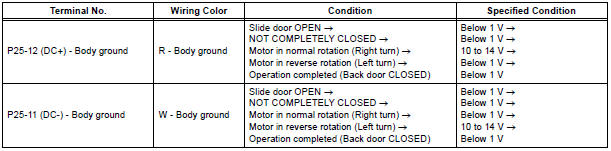
If the result is not as specified, the ECU may have a malfunction.
2. CHECK POWER SLIDE DOOR ECU RH
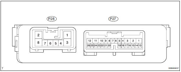
- Disconnect the P27 and P28 ECU connectors, and check the voltage and resistance of each terminal of the wire harness side connectors.

If the result is not as specified, there may be a malfunction on the wire harness side.
- Reconnect the ECU connectors, and check the voltage of each terminal of the connectors.
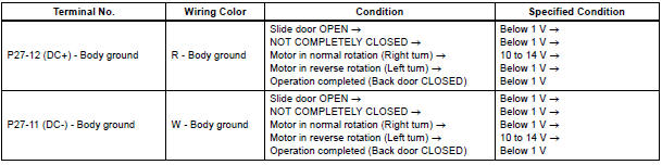
If the result is not as specified, the ECU may have a malfunction.
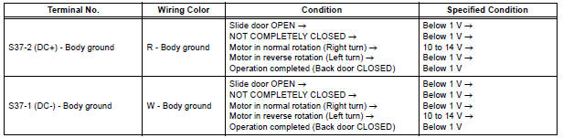
3. CHECK SLIDE DOOR CLOSER RELAY LH (WITHOUT POWER SLIDE DOOR)
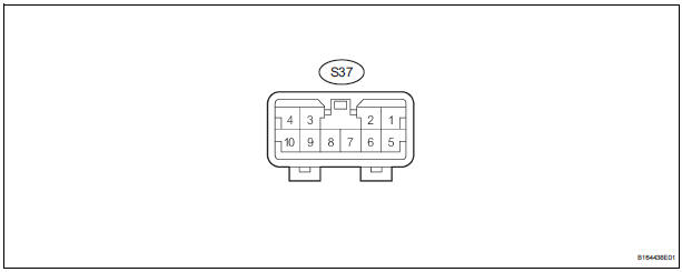
- Disconnect the S37 relay connector, and check the voltage and resistance of each terminal of the wire harness side connectors.
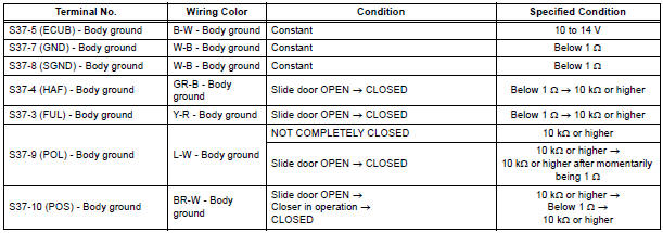
If the result is not as specified, there may be a malfunction on the wire harness side.
- Reconnect the relay connector, and check the voltage of each terminal of the connectors.
If the result is not as specified, the relay may have a malfunction.
 Problem symptoms table
SLIDE DOOR CLOSER SYSTEM
Symptom
Suspected Area
Slide door closer LH does not operate (*1)
ECU-B fuse
Power slide door lock assembly LH
Power slide do ...
 Diagnosis system
1. CHECK DLC3
The vehicle's ECU uses ISO 15765-4 for
communication protocol. The terminal arrangement
of the DLC3 complies with SAE J1962 and matches
the ISO 15765-4 format.
NOT ...
Other materials:
Stereo Component Amplifier Communication Error
INSPECTION PROCEDURE
1 IDENTIFY THE COMPONENT SHOWN BY THE SUB-CODE
Enter the diagnostic mode.
Press the preset switch "3" to change to "Detailed
Information Mode".
Identify the component shown by the sub-code.
HINT:
"190 (radio receiver ...
Problem symptoms table
Vehicle stability control system:
TERMINALS OF ECU
1. Terminal of ECU
(*1): Models with dynamic laser cruise control
(*2): 2WD model
2. Terminal Inspection
(a) Disconnect the connector and measure the voltage or resistance on the wire harness side.
HINT: Voltage cannot be measured wit ...
Installation
1. INSTALL REAR AXLE BEAM DAMPER
(a) Install the rear axle beam damper to the rear axle
beam assembly.
2. INSTALL REAR AXLE CARRIER BUSH LH
(a) Align the matchmarks on the axle beam assembly
with the 2 notches of a new bushing and temporarily
install the bushing to the rear axle beam assem ...
