Toyota Sienna Service Manual: Front Clearance Sonar Sensor RH Circuit
DESCRIPTION
An ultrasonic sensor consists of a sensor portion that transmits and receives ultrasonic waves and a preamplifier that amplifies them. The ultrasonic sensor outputs the ultrasonic waves and sends the reveiced signals to the clearance warning ECU.
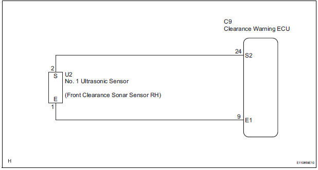
WIRING DIAGRAM
INSPECTION PROCEDURE
1 INSPECT NO. 1 ULTRASONIC SENSOR
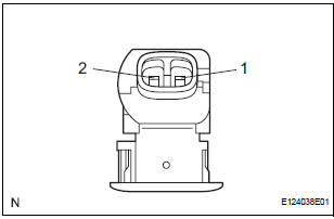
- Remove the No. 1 ultrasonic sensor.
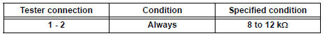
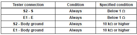
- Measure the resistance according to the value(s) in the table below.
Standard resistance
2 CHECK HARNESS AND CONNECTOR (CLEARANCE WARNING ECU - NO. 1 ULTRASONIC SENSOR)
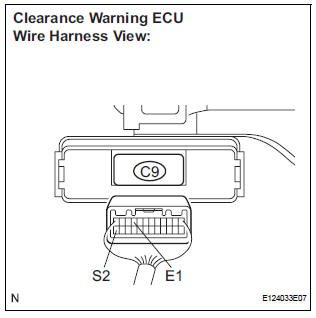
- Disconnect the C9 connector from the clearance warning ECU.
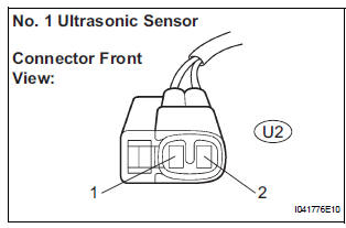
- Disconnect the U2 connector from the No. 1 ultrasonic sensor.
- Measure the resistance according to the value(s) in the table below.
Standard resistance
PROCEED TO NEXT CIRCUIT INSPECTION SHOWN IN PROBLEM SYMPTOMS TABLE
 Front Clearance Sonar Sensor LH Circuit
DESCRIPTION
An ultrasonic sensor consists of a sensor portion that transmits and receives
ultrasonic waves and a preamplifier
that amplifies them. The ultrasonic sensor outputs the ultrasonic wave ...
 Rear Clearance Sonar Sensor LH Circuit
DESCRIPTION
An ultrasonic sensor consists of a sensor portion that transmits and receives
ultrasonic waves and a preamplifier
that amplifies them. The ultrasonic sensor outputs the ultrasonic wave ...
Other materials:
Repair
1. INTRODUCTION
(a) This section introduces ways to determine whether
the run-flat tire is repairable or not. Repair must be
performed by following the appropriate procedures.
If a flat tire occurs, it is possible to drive a maximum
of 160 km (100 miles) at a speed below 90 km/h (55
mph) due ...
Diagnostic trouble code chart
COMMUNICATION DIAGNOSIS:
SW:
SW WITH NAME:
SW CONVERTING:
COMMAND SW:
FRONT MONITOR:
DVD PLAYER:
TELEPHONE:
NAVI:
IN-DASH CD CHANGER:
GPS:
CAMERA UNIT:
...
Noise Occurs from Generator while Engine is Running
INSPECTION PROCEDURE
1 CHECK LOOSENESS OF V-RIBBED BELT
(a) Check the tension of the belt by pushing it down with a
finger.
OK:
The tension of the belt is enough.
2 CHECK V-RIBBED BELT FOR WEAR
(a) Check the V-ribbed belt for wear.
OK:
The V-ribbed belt is not worn.
3 CHECK CLUTC ...
