Toyota Sienna Service Manual: Reassembly
1. INSTALL NO. 2 SEAT LEG SUB-ASSEMBLY
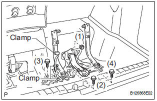
- Install the No. 2 seat leg sub-assembly with the 3
bolts and nut.
Torque: 19 N*m (194 kgf*cm, 14 ft.*lbf)
NOTICE: Tighten the bolts and nuts in the order shown in the illustration.
- Install the 3 clamps.
2. INSTALL NO. 2 SEAT CUSHION FRAME SUBASSEMBLY
3. INSTALL NO. 2 SEAT CUSHION SPRING ASSEMBLY
4. INSTALL NO. 2 SEAT CUSHION STOPPER
5. INSTALL REAR SEAT WIRE
6. INSTALL NO. 2 SEAT CUSHION PAD
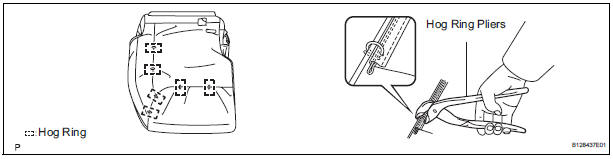
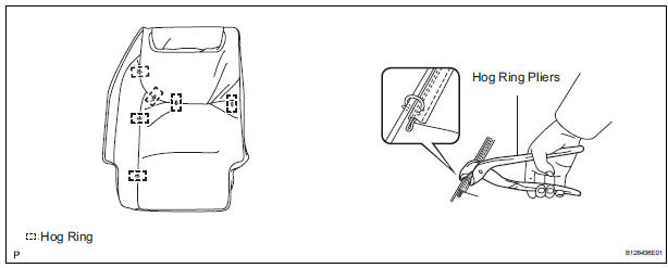
7. INSTALL NO. 2 SEAT CUSHION COVER SUBASSEMBLY
- Using hog ring pliers, install the No. 2 seat cushion cover sub-assembly to the No. 2 seat cushion pad with 6 new hog rings.
NOTICE:
- Be careful not to damage the cover.
- When installing the hog rings, take care to minimize wrinkles as much as possible.
8. INSTALL NO. 2 SEAT CUSHION COVER SUBASSEMBLY WITH PAD
9. INSTALL REAR SEAT COVER
10. INSTALL REAR NO. 2 SEAT BELT ASSEMBLY INNER
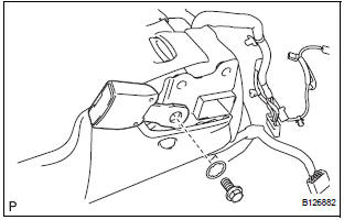
- Install the rear No. 2 seat belt assembly inner with
the bolt and washer.
Torque: 44 N*m (449 kgf*cm, 33 ft.*lbf)
11. INSTALL REAR POWER SEAT SWITCH
12. INSTALL RECLINING REMOTE CONTROL LEVER BEZEL
13. INSTALL NO. 2 SEATBACK FRAME SUB-ASSEMBLY
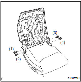
- Install the No. 2 seatback frame sub-assembly with
the 4 bolts.
Torque: 44 N*m (449 kgf*cm, 33 ft.*lbf)
NOTICE:
- Tighten the bolts in the following order:
- Temporarily tighten bolt (1).
- Temporarily tighten bolt (2).
- Fully tighten bolt (3).
- Fully tighten bolt (4).
- Fully tighten bolt (1).
- Fully tighten bolt (2).
14. INSTALL FOLD SEAT CONTROL ECU
15. INSTALL NO. 2 SEATBACK PAD
16. INSTALL NO. 2 SEATBACK COVER SUB-ASSEMBLY
- Using hog ring pliers, install the No. 2 seatback cover sub-assembly to the No. 2 seatback pad with 6 new hog rings.
NOTICE:
- Be careful not to damage the cover.
- When installing the hog rings, take care to minimize wrinkles as much as possible
17. INSTALL NO. 2 SEATBACK COVER SUB-ASSEMBLY WITH PAD
18. INSTALL REAR NO. 2 SEAT HEADREST SUPPORT ASSEMBLY RH
19. INSTALL REAR NO. 2 SEAT HEADREST SUPPORT ASSEMBLY LH
20. INSTALL REAR SEAT HEADREST ASSEMBLY
21. INSTALL REAR SEAT RECLINING COVER RH
22. INSTALL REAR SEAT RECLINING COVER LH
23. INSTALL REAR NO. 2 SEAT COVER BEZEL
 Adjustment
HINT:
If the malfunction does not disappear by following the
procedure in ADJUSTMENT and the rear No. 2 seat
assembly needs to be replaced, do not disassemble the rear
No. 2 seat assembly.
1. ADJ ...
 Installation
1. INSTALL REAR NO. 2 SEAT ASSEMBLY
Lock the seat leg rear to the floor striker.
Lock the seat leg front to the floor striker.
Install the rear No. 2 seat assembly with t ...
Other materials:
Ambient temperature sensor circuit
DTC B1412/12 Ambient Temperature Sensor Circuit
DESCRIPTION
The ambient temperature sensor is installed in front of the condenser to
detect the ambient temperature
which is used to control the air conditioner "AUTO" mode. This sensor is
connected to the A/C amplifier
and detects fl ...
Preparation 2gr-fe cooling
SST
RECOMMENDED TOOLS
EQUIPMENT
COOLANT
Capacity
Classification
11.3 liters (12.0 US qts, 10.0 Imp. qts)
Use only "TOYOTA Super Long Life Coolant" or similar high quality
ethylene glycol based non-silicate, non-amine, non-nitrite, non-borate
coolant ...
Replacement
1. DISCHARGE REFRIGERANT FROM
REFRIGERATION SYSTEM
SST 07110-58060 (07117-58080, 07117-58090,
07117-78050, 07117-88060, 07117-88070,
07117-88080)
(a) Turn the A/C switch to ON.
(b) Operating the cooler compressor at the engine rpm
of approx. 1,000 for 5 to 6 minutes, circulate the
refriger ...
