Toyota Sienna Service Manual: Terminals of ECU
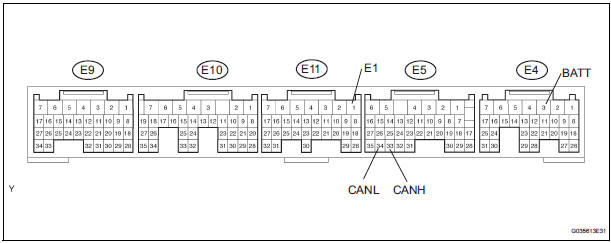
1. JUNCTION CONNECTOR
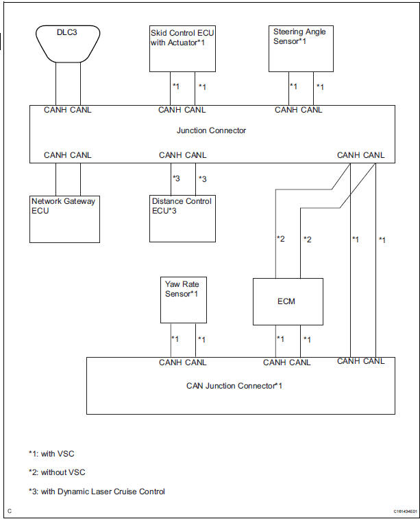
- Junction connector
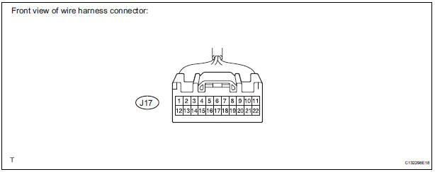
with VSC
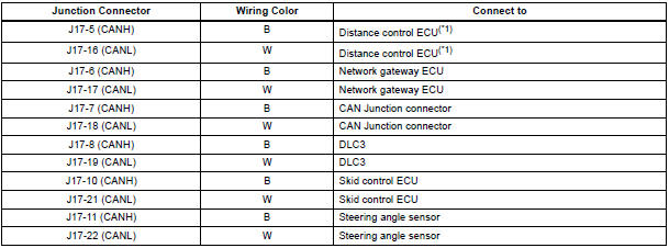
HINT: *1: with Dynamic laser cruise control
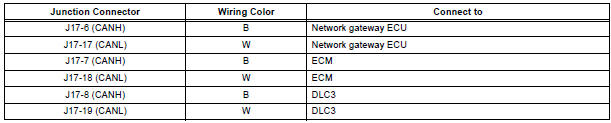
without VSC
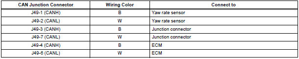
- CAN junction connector (with VSC)
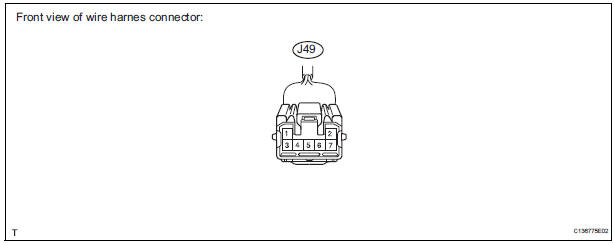
with VSC
- The connection diagram of the components which are connected to the CAN junction connector.
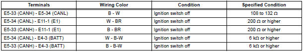
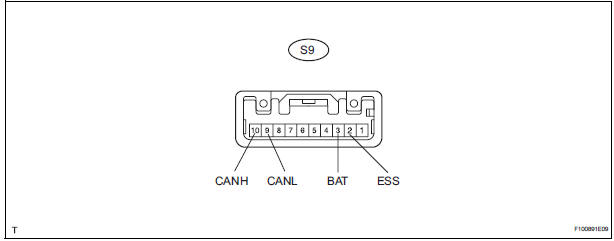
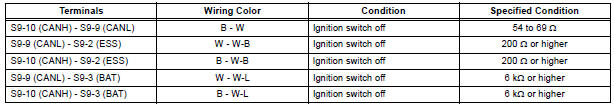
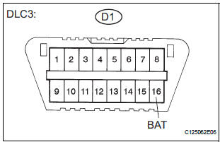
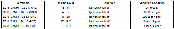
2. DLC3
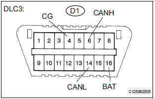
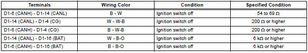
- Measure the resistance according to the value(s) in the table below.
Standard resistance
3. ECM
- Disconnect the connector from the ECM.
- Measure the resistance according to the value(s) in the table below
Standard resistance
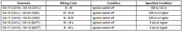
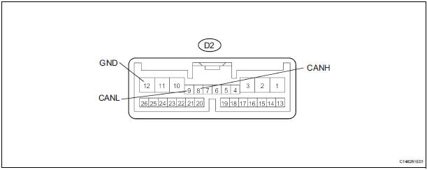
4. NETWORK GATEWAY ECU
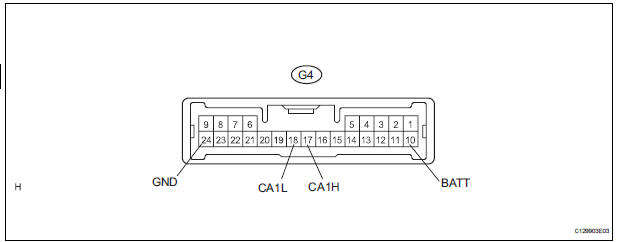
- Disconnect the connector from the netwark gateway ECU.
- Measure the resistance according to the value(s) in the table below
Standard resistance
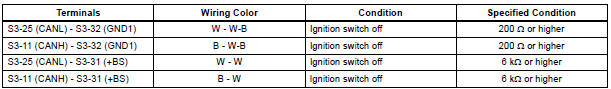
5. SKID CONTROL ECU WITH ACTUATOR
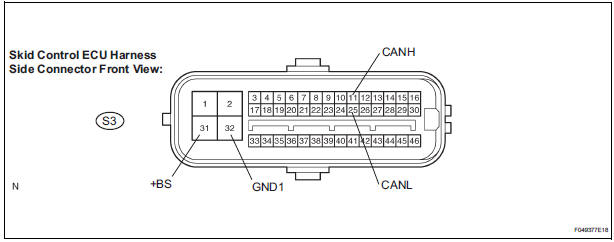
- Disconnect the connector from the skid control ECU with actuator.
- Measure the resistance according to the value(s) in the table below
Standard resistance

6. STEERING ANGLE SENSOR
- Disconnect the connector from the steering angle sensor.
- Measure the resistance according to the value(s) in the table below.
Standard resistance
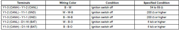
7. YAW RATE SENSOR
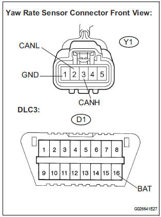
- Disconnect the connector from the yaw rate sensor.
- Measure the resistance according to the value(s) in the table below.
Standard resistance
8. DISTANCE CONTROL ECU
- Disconnect the connector from the distance control ECU.
- Measure the resistance according to the value(s) in the table below.
Standard resistance
 Problem symptoms table
RESULT LIST OF CHECK CAN BUS LINE
Symptom
Suspected Area
All ECUs and sensors connected to the CAN
communication system are not displayed on intelligent
tester
CAN ...
 Diagnosis system
1. BUS CHECK
Select "BUS CHECK" from the "OBD/MOBD
MENU" screen.
HINT:
The ECUs and sensors that are properly connected
to the CAN communication system can be displaye ...
Other materials:
Diagnostic trouble code chart
1. DTCS FOR OCCUPANT CLASSIFICATION SYSTEM
If a trouble code is displayed during the DTC check,
check the circuit listed for the code in the table below
(proceed to the page listed for that circuit).
HINT:
When DTC B1150/23 is detected as a result of
troubleshooting for the airbag system, pe ...
Differential
SST
RECOMMENDED TOOLS
EQUIPMENT
LUBRICANT
SSM
...
Displaying a Bluetooth®
device details
You can confirm and change the registered device details.
Bluetooth® device registration status
Display the ÔÇťBluetooth* SetupÔÇŁ screen.
*: Bluetooth is a registered trademark of Bluetooth SIG, Inc.
Select the device.
Select ÔÇťDevice InfoÔÇŁ.
Following screen is displayed:
...
