Toyota Sienna Service Manual: Disassembly
1. Remove rear wheel
2. Drain brake fluid
Notice: wash the brake fluid off immediately if it attaches to any painted surface.
3. REMOVE REAR BRAKE DRUM SUB-ASSEMBLY
(a) Release the parking brake lever, and remove the rear brake drum.
HINT: If the rear brake drum cannot be removed easily, perform the following procedure.
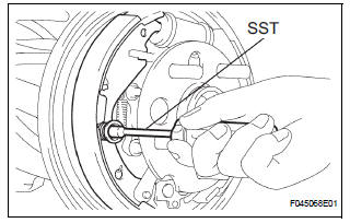
(b) Remove the hole plug and insert a screwdriver through the hole in the backing plate, and hold the automatic adjusting lever away from the adjuster.
(c) Using another screwdriver, reduce the brake shoe adjuster by turning the adjusting wheel.
4. REMOVE FRONT BRAKE SHOE
(a) Using SST, remove the shoe return spring from the front brake shoe.
SST 09921-00010
(b) Using a needle-nose pliers, remove the return spring.
(c) Using SST, remove the shoe hold down spring cup, shoe hold down spring and pin.
SST 09718-00010 (d) Remove the parking brake shoe strut LWR.
(e) Remove the tension spring and front brake shoe.
(f) Remove the automatic adjust lever spring and rear brake automatic adjust lever LH from the front brake shoe.
5. REMOVE REAR BRAKE SHOE
(a) Using SST, remove the shoe hold down spring cup, shoe hold down spring and pin.
SST 09718-00010
(b) Using a needle-nose pliers, disconnect the parking brake cable No. 3 and remove the rear brake shoe.
(c) Using a screwdriver, remove the 2 C-washers, parking brake shoe lever, parking brake reaction lever LH and rear brake strut set.
6. REMOVE LH, FRONT OR UPPER REAR WHEEL BRAKE CYLINDER ASSEMBLY
(a) Using SST, disconnect the brake tube, use a container to catch the brake fluid.
SST 09023-00101
(b) Remove the 2 bolts and rear wheel brake cylinder assembly.
7. REMOVE REAR WHEEL CYLINDER CUP KIT
(a) Remove the 2 cylinder dust boots from the rear wheel brake cylinder assembly.
(b) Remove the 2 pistons and compression spring.
(c) Remove the 2 wheel cylinder cups from each piston.
(d) Remove the bleeder plug cap and bleeder plug from the rear wheel brake cylinder assembly.
 Rear drum brake
Components
...
 Inspection
1. INSPECT BRAKE DRUM INSIDE DIAMETER
(a) Using a brake drum gauge or equivalent, measure
the inside diameter of the drum.
Standard inside diameter:
254.0 mm (10.00 in.)
Maximum inside diamet ...
Other materials:
Cleaning and protecting
the vehicle interior
The following procedures will help protect your vehicle’s interior
and keep it in top condition:
Protecting the vehicle interior
Remove dirt and dust using a vacuum cleaner. Wipe dirty surfaces
with a cloth dampened with lukewarm water.
Cleaning the leather areas
Remove dirt and dust usin ...
Open in CAN Main Bus Line
DESCRIPTION
There may be an open circuit in the CAN main bus wire and/or the DLC3 branch
wire when the resistance
between terminals 6 (CANH) and 14 (CANL) of the DLC3 is 69 Ω or higher.
Symptom
Trouble Area
Resistance between terminals 6 (CANH) and 14 (CANL) of t ...
Reclining Motor Circuit
DESCRIPTION
The fold seat control ECU receives a switch operation signal from the power
rear no. 2 seat switch and
the fold seat switch, and activates the reclining motor. At this time, the Hall
IC (seatback position sensor)
detects the actuation of the seatback and sends a seatback actuation ...
