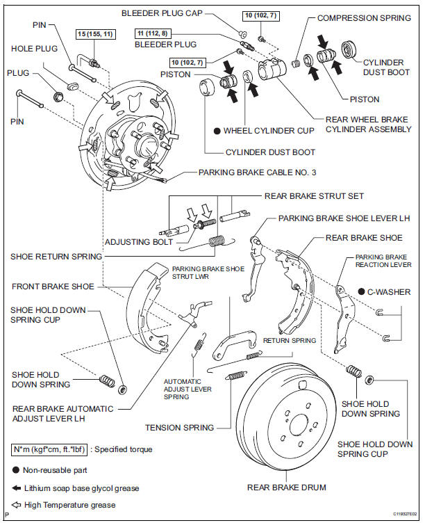
Toyota Sienna Service Manual: Rear drum brake
Components
 Installation
HINT:
Install the RH side by the same procedure as the LH side.
1. INSTALL REAR DISC BRAKE CYLINDER MOUNTING
LH
(a) Install the rear disc brake cylinder mounting LH with
the 2 bolts.
Torque: 8 ...
 Disassembly
1. Remove rear wheel
2. Drain brake fluid
Notice:
wash the brake fluid off immediately if it attaches to
any painted surface.
3. REMOVE REAR BRAKE DRUM SUB-ASSEMBLY
(a) Release the parking brake ...
Other materials:
Short in Rear Curtain Shield Squib LH Circuit
DTC B1635/87 Short in Rear Curtain Shield Squib LH Circuit
DESCRIPTION
The rear curtain shield squib LH circuit consists of the center airbag sensor
assembly and the curtain
shield airbag assembly LH.
The circuit instructs the SRS to deploy when deployment conditions are met.
DTC B1635/87 ...
Installation
1. INSTALL FRONT BUMPER ASSEMBLY
Push the front bumper onto the front of the vehicle
and engage the claws on the left and right sides of
the front bumper to install it as shown in the
illustration.
HINT:
Apply protective tape to the bottom part of the
front fender to prevent i ...
Air outlet control servo motor
ON-VEHICLE INSPECTION
1. INSPECT AIR OUTLET CONTROL SERVO MOTOR
(a) Remove the air outlet control servo motor.
(b) Connect the positive (+) lead from the battery to
terminal 4 and negative (-) lead to terminal 5, then
check that the lever turns to "DEF" position.
(c) Connect ...
