Toyota Sienna Service Manual: Disassembly
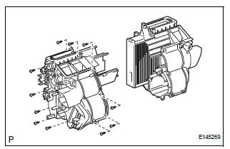
1. REMOVE BLOWER ASSEMBLY
(a) Remove the 2 screws and the blower assembly.
2. REMOVE MODE DAMPER SERVO SUB-ASSEMBLY
(a) Remove the 3 screws and the mode damper servo sub-assembly.
3. REMOVE AIRMIX DAMPER SERVO SUB-ASSEMBLY
(a) Remove the 3 screws and the airmix damper servo sub-assembly.
4. REMOVE NO. 2 AIRMIX DAMPER SERVO SUBASSEMBLY (for Automatic Air Conditioning System)
(a) Remove the 3 screws and the No. 2 airmix damper servo sub-assembly.
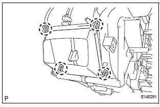
5. REMOVE NO. 1 HEATER CLAMP
(a) Release the 4 claw fittings and remove the No. 1 heater clamp.
6. REMOVE NO. 3 AIR CONDITIONING RADIATOR BRACKET
(a) Remove the screw and the No. 3 air conditioning radiator bracket.
7. REMOVE HEATER RADIATOR UNIT SUB-ASSEMBLY
(a) Remove the heater radiator unit sub-assembly from the air conditioning radiator assembly.
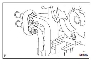
8. REMOVE AIR CONDITIONING TUBE ASSEMBLY
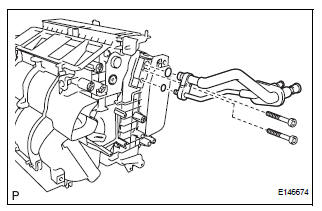
(a) Using a hexagon wrench 4.0 mm (0.15 in.), remove the 2 hexagon bolts and the air conditioning tube assembly.
(b) Remove the 2 O-rings from the air conditioning tube assembly.
9. REMOVE COOLER EXPANSION VALVE
(a) Remove the cooler expansion valve from the No. 1 cooler evaporator sub-assembly.
(b) Remove the 2 O-rings from the No. 1 cooler evaporator sub-assembly.
10. REMOVE NO. 2 AIR CONDITIONING RADIATOR BRACKET
(a) Remove the 2 screws and the No. 2 air conditioning radiator bracket.
11. REMOVE NO. 1 AIR CONDITIONING RADIATOR BRACKET
(a) Remove the 3 screws and the No .1 air conditioning radiator bracket.
12. REMOVE NO. 4 AIR CONDITIONING RADIATOR BRACKET
(a) Remove the No. 4 air conditioning radiator bracket.
13. REMOVE NO. 1 AIR DUCT
(a) Release the 4 claw fittings and remove the No. 1 air duct.
14. REMOVE NO. 1 COOLER THERMISTOR
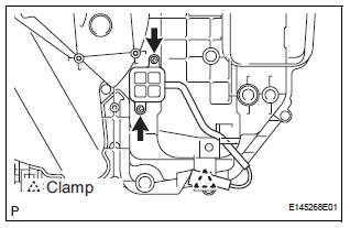
(a) Disengage the clamp.
(b) Remove the 2 screws.
(c) Remove the 11 screws.
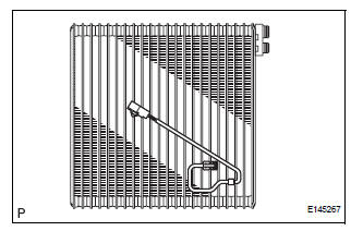
(d) Remove the No. 1 cooler thermistor.
 Removal
1. RECOVER REFRIGERANT FROM REFRIGERATION
SYSTEM (See page AC-172)
2. REMOVE FRONT WIPER ARM HEAD CAP (See page
WW-4)
3. REMOVE FRONT WIPER ARM RH (See page WW-4)
4. REMOVE FRONT WIPER ARM LH (Se ...
 Reassembly
1. INSTALL NO. 1 COOLER THERMISTOR
(a) Install the No. 1 cooler thermistor as shown in the
illustration.
NOTICE:
Be sure to insert the thermistor only once
because reinserting it will no ...
Other materials:
Folding and extending the mirrors
Manual type
Push the mirror back in the direction
of the vehicle’s rear.
Power type
Press the switch.
Folding
Extending
...
Installation
1. INSTALL SEAT POSITION AIRBAG SENSOR
Check that the ignition switch is off.
Check that the negative battery (-) terminal is
disconnected.
CAUTION:
After disconnecting the negative battery
terminal, wait for at least 90 seconds before
starting the operation.
Usin ...
Reassembly
NOTICE:
Before installation, coat the parts indicated by arrows
with power steering fluid (See page PS-7).
1. INSTALL VANE PUMP HOUSING OIL SEAL
(a) Coat a new vane pump housing oil seal lip with
power steering fluid.
(b) Using SST and a press, install the vane pump
housing oil seal until i ...
