Toyota Sienna Service Manual: Reassembly
1. INSTALL NO. 1 COOLER THERMISTOR
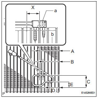
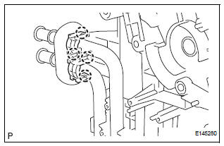
(a) Install the No. 1 cooler thermistor as shown in the
illustration. 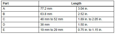
NOTICE:
- Be sure to insert the thermistor only once because reinserting it will not allow it to be firmly secured.
- When reusing the evaporator, insert the thermistor one row next to the one that had been used previously (X in the illustration).
- After inserting the thermistor, do not apply excessive force to the wire.
- Directly insert the thermistor until the edge of plastic case "a" comes into contact with evaporator "b".
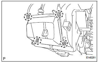
(b) Install the 11 screws.
(c) Install the 2 screws.
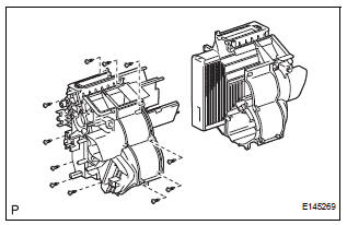
(d) Engage the clamp.
2. INSTALL NO. 1 AIR DUCT
(a) Engage the 4 claws and install the No. 1 air duct.
3. INSTALL NO. 4 AIR CONDITIONING RADIATOR BRACKET
4. INSTALL NO. 1 AIR CONDITIONING RADIATOR BRACKET
(a) Install the No. 1 air conditioning radiator bracket with the 3 screws.
5. INSTALL NO. 2 AIR CONDITIONING RADIATOR BRACKET
(a) Install the No. 2 air conditioning radiator bracket with the 2 screws.
6. INSTALL COOLER EXPANSION VALVE
(a) Sufficiently apply compressor oil to 2 new O-rings and the fitting surface of the No. 1 cooler evaporator sub-assembly.
Compressor oil: ND-OIL 8 or equivalent
(b) Install the cooler expansion valve to the No. 1 cooler evaporator sub-assembly.
7. INSTALL AIR CONDITIONING TUBE ASSEMBLY
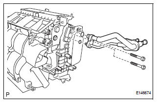
(a) Sufficiently apply compressor oil to 2 new O-rings and the fitting surface of the air conditioning tube assembly.
Compressor oil: ND-OIL 8 or equivalent
(b) Install the 2 O-rings on the air conditioning tube assembly.
(c) Using a hexagon wrench 4.0 mm (0.15 in.), install the air conditioning tube assembly with the 2 hexagon bolts.
Torque: 3.5 N*m (35 kgf*cm, 30 in.*lbf)
8. INSTALL HEATER RADIATOR UNIT SUB-ASSEMBLY
(a) Install the heater radiator unit sub-assembly to the air conditioning radiator assembly.
9. INSTALL NO. 3 AIR CONDITIONING RADIATOR BRACKET
(a) Install the No. 3 air conditioning radiator bracket with the screw.
10. INSTALL NO. 1 HEATER CLAMP
(a) Engage the 4 claws and install the No. 1 heater clamp.
11. INSTALL NO. 2 AIRMIX DAMPER SERVO SUBASSEMBLY (for Automatic Air Conditioning System)
(a) Install the No. 2 airmix damper servo sub-assembly with the 3 screws.
12. INSTALL AIRMIX DAMPER SERVO SUB-ASSEMBLY
(a) Install the airmix damper servo sub-assembly with the 3 screws.
13. INSTALL MODE DAMPER SERVO SUB-ASSEMBLY
(a) Install the mode damper servo sub-assembly with the 3 screws.
14. INSTALL BLOWER ASSEMBLY
(a) Install the blower assembly with the 2 screws.
 Disassembly
1. REMOVE BLOWER ASSEMBLY
(a) Remove the 2 screws and the blower assembly.
2. REMOVE MODE DAMPER SERVO SUB-ASSEMBLY
(a) Remove the 3 screws and the mode damper servo
sub-assembly.
3. REMO ...
 Installation
1. TEMPORARILY TIGHTEN AIR CONDITIONING UNIT ASSEMBLY
(a) Engage the 2 claws.
(b) Temporarily tighten the air conditioning unit
assembly with the nut.
Torque: 9.8 N*m (100 kgf*cm, 87 in.*lbf ...
Other materials:
Auto Up Operation does not Fully Close Power Window (Jam
Protection Function is Activated)
DESCRIPTION
If AUTO UP operation does not fully close the power window, the following
conditions may be the cause.
The reset of the power window motor has not been completed,
resulting in activation of the jam
protection function.
The memory of the power window switch misse ...
Air Inlet Damper Position Sensor Circuit
DESCRIPTION
This sensor detects the position of the air inlet control servo motor and
sends the appropriate signals to
the A/C amplifier. The position sensor is built in the air inlet control servo
motor.
The position sensor's resistance changes as the air inlet control servo motor
ar ...
Removal
1. PRECAUTION
CAUTION: Be sure to read "PRECAUTION" thoroughly before
servicing.
2. DISCONNECT CABLE FROM NEGATIVE BATTERY
TERMINAL
CAUTION:
Wait for 90 seconds after disconnecting the cable to
prevent the airbag working.
3. REMOVE STEERING WHEEL NO.3 COVER LOWER
Using a ...
