Toyota Sienna Service Manual: Removal
1. RECOVER REFRIGERANT FROM REFRIGERATION SYSTEM (See page AC-172)
2. REMOVE FRONT WIPER ARM HEAD CAP (See page WW-4)
3. REMOVE FRONT WIPER ARM RH (See page WW-4)
4. REMOVE FRONT WIPER ARM LH (See page WW-4)
5. REMOVE COWL TOP VENTILATOR LOUVER SUBASSEMBLY (See page WW-4)
6. REMOVE WINDSHIELD WIPER MOTOR AND LINK ASSEMBLY (See page WW-4)
7. REMOVE FRONT COWL TOP OUTER PANEL SUBASSEMBLY (See page SP-13)
8. DISCONNECT COOLER REFRIGERANT LIQUID PIPE E (TO COOLER UNIT)
(a) Install SST on the piping clamp.
SST 09870-00025
HINT: Make sure the direction of the piping clamp claw and SST by checking the illustration shown on the caution label.
(b) Push down SST and release the clamp lock.
NOTICE: Be careful not to deform the tube when pushing SST.
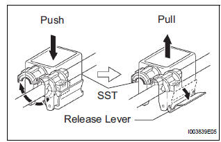
(c) Pull SST slightly, push the release lever, and then remove the piping clamp with SST.
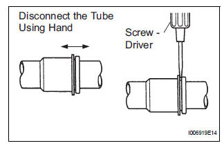
(d) Disconnect the cooler refrigerant liquid pipe (to cooler unit).
NOTICE:
- Do not use any tools like a screwdriver to remove the tube.
- Seal the openings of the disconnected parts using vinyl tape to prevent entry of moisture and foreign matter.
9. DISCONNECT SUCTION HOSE SUB-ASSEMBLY SST 09870-00015
HINT: Disconnection of the pipe cooler refrigerant suction hose sub-assembly is the same way as the cooler refrigerant liquid pipe E (to cooler unit).
10. REMOVE AIR CLEANER CAP SUB-ASSEMBLY (See page IT-4)
11. DISCONNECT HEATER WATER OUTLET HOSE A (FROM HEATER UNIT)
(a) Using pliers, grip the claws of the clip and slide the clip to disconnect the heater water outlet hose A (from heater unit).
12. REMOVE HEATER WATER INLET HOSE A
HINT: Disconnection of the heater water inlet hose A is the same way as the heater water outlet hose A (from heater unit).
13. REMOVE INSTRUMENT PANEL SUB-ASSEMBLY WITH PASSENGER AIRBAG ASSEMBLY
HINT: Refer to the instructions for removal of the instrument panel sub-assembly with passenger airbag assembly (See page IP-5).
14. REMOVE SPIRAL CABLE (See page RS-434)
15. REMOVE NO. 3 HEATER TO FOOT DUCT
(a) Remove the clip and the No. 3 heater to foot duct.
16. REMOVE NO. 1 HEATER TO FOOT DUCT
(a) Remove the clip and the No. 1 heater to foot duct.
17. DISCONNECT TRANSMISSION CONTROL CABLE ASSEMBLY
HINT: (See page AX-154 for U151E, AX-154 for U151F)
18. REMOVE SHIFT LEVER ASSEMBLY
HINT: (See page AX-147 for U151E, AX-147 for U151F)
19. REMOVE NO. 5 INSTRUMENT PANEL BRACKET
(a) Release the 2 clamps and disconnect the connector.
(b) Remove the 4 nuts and the No. 5 instrument panel bracket.
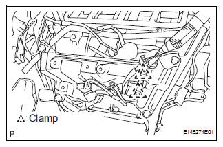
20. REMOVE NO. 1 INSTRUMENT PANEL BRACE SUBASSEMBLY
(a) Release the 4 clamps and remove the bolt.
(b) Disconnect the connector.
(c) Remove the 3 bolts, the 2 nuts and the No. 1 instrument panel brace sub-assembly.
21. REMOVE NO. 2 INSTRUMENT PANEL BRACE SUBASSEMBLY
(a) Release the 2 clamps and disconnect the connector.
(b) Remove the 3 bolts, the 2 nuts and the No. 2 instrument panel brace sub-assembly.
22. SEPARATE STEERING INTERMEDIATE SHAFT ASSEMBLY (See page SR-7)
23. REMOVE STEERING COLUMN ASSEMBLY (See page SR-7)
24. REMOVE STEREO COMPONENT AMPLIFIER ASSEMBLY (w/ Stereo Component Amplifier) (See page AV-173)
25. REMOVE ECM (See page ES-498)
26. REMOVE FRONT FENDER GARNISH RH
HINT: See page ET-35
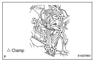
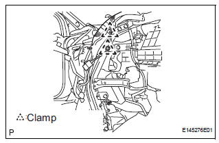
27. REMOVE INSTRUMENT PANEL REINFORCEMENT
(a) Remove the 6 nuts.
(b) Release the 13 clamps.
(c) Remove the screw.
(d) Disconnect the connectors.
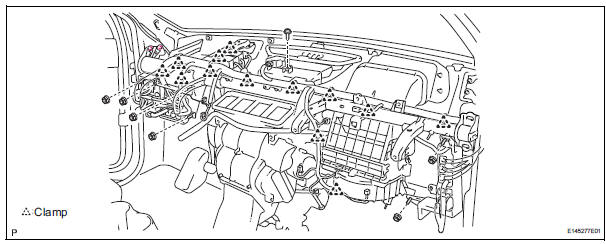
(e) Remove the 11 bolts, 2 nuts and the instrument panel reinforcement.
28. REMOVE LOWER DEFROSTER NOZZLE ASSEMBLY
(a) Release the 4 claw fittings and remove the lower defroster nozzle assembly.
29. REMOVE AIR CONDITIONING UNIT ASSEMBLY
(a) Release the 2 claw fittings and remove the nut and the air conditioning unit assembly.
 Air conditioning unit
COMPONENTS
...
 Disassembly
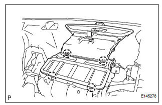
1. REMOVE BLOWER ASSEMBLY
(a) Remove the 2 screws and the blower assembly.
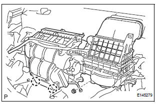
2. REMOVE MODE DAMPER SERVO SUB-ASSEMBLY
(a) Remove the 3 screws and the mode damper servo
sub-assembly.
3. REMO ...
Other materials:
Engine coolant temperature sensor
COMPONENTS
REMOVAL
1. DRAIN ENGINE COOLANT (See page CO-6)
2. REMOVE V-BANK COVER SUB-ASSEMBLY (See
page EM-28)
3. REMOVE NO. 2 AIR CLEANER INLET (See page EM-
28)
4. REMOVE NO. 1 AIR CLEANER INLET (See page EM-
28)
5. REMOVE AIR CLEANER CAP SUB-ASSEMBLY (See
page ES-493)
6. REMOVE AI ...
Disassembly
1. INSPECT UNDERDRIVE PACK CLEARANCE
HINT:
(See page AX-262)
2. REMOVE UNDERDRIVE CLUTCH FLANGE NO.2 HOLE
SNAP RING
a) Using a screwdriver, remove the underdrive clutch
flange No.2 snap ring.
3. REMOVE UNDERDRIVE CLUTCH DISC NO.1
(a) Remove the flange, 4 discs and 4 plates from the
...
Removal
HINT:
On the LH side, use the same procedures as on the RH side.
1. REMOVE FRONT DOOR SCUFF PLATE RH
Using a screwdriver, disengage the 3 clips and 2
claws, and remove the scuff plate.
HINT:
Tape the screwdriver tip before use.
2. REMOVE FRONT DOOR SCUFF PLATE LH
3. REMOVE REAR DOO ...
