Toyota Sienna Service Manual: Disassembly
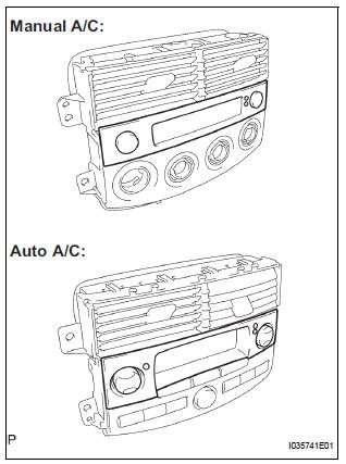
1. REMOVE CENTER CLUSTER MODULE KNOB NO.1 (for Manual Air Conditioning System)
(a) Remove the center cluster module knob No. 1.
2. REMOVE CENTER CLUSTER MODULE KNOB NO.2 (for Manual Air Conditioning System)
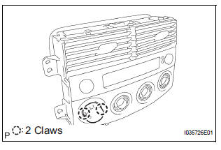
(a) Release the 2 claws fittings and remove the center cluster module knob No. 2.
NOTICE: Take care not to break the claws on the knob.
3. REMOVE AIR CONDITIONER AMPLIFIER ASSEMBLY (for Manual Air Conditioning System)
(a) Remove the plate.
(b) Release the lock of the connector and disconnect the cable.
(c) Remove the 4 screws, and the heater control housing.
(d) Remove the 4 screws, and the air conditioner amplifier assembly.
4. REMOVE AIR CONDITIONER AMPLIFIER ASSEMBLY (for Automatic Air Conditioning System)
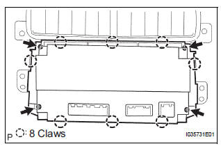
(a) Release the 8 claw fittings and remove the 4 screws and the heater control housing.
(b) Disconnect the 2 connectors.
(c) Remove the 5 screws and the air conditioner amplifier assembly.
5. REMOVE INTEGRATION CONTROL AND PANEL BULB (for Manual Air Conditioning System)
(a) Remove the integration control & panel bulb.
6. REMOVE HEATER BLOWER SWITCH (for Manual Air Conditioning System)
(a) Remove the 3 nuts, and the 3 washers.
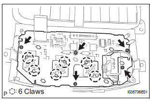
(b) Release the 6 claw fittings and remove the 5 screws and printed wire integration board sub-assembly.
(c) Remove the screw and the heater blower switch.
7. REMOVE PRINTED WIRE INTEGRATION BOARD SUB-ASSEMBLY (for Automatic Air Conditioning System)
(a) Remove the 12 screws and the printed wire integration board sub-assembly.
8. REMOVE CLOCK ORNAMENT
(a) Remove the clock ornament
9. REMOVE CENTER CLUSTER MODULE KNOB NO.5 (for Automatic Air Conditioning System)
10. REMOVE CENTER CLUSTER MODULE KNOB NO.6 (for Automatic Air Conditioning System)
 Removal
1. REMOVE INSTRUMENT CLUSTER FINISH PANEL
CENTER NO.1 (See page IP-8)
2. REMOVE INSTRUMENT CLUSTER FINISH PANEL
CENTER NO.2
3. REMOVE SHIFT LEVER KNOB SUB-ASSEMBLY
HINT:
(See page AX-146 for U15 ...
 Reassembly
1. INSTALL CENTER CLUSTER MODULE KNOB NO.6
(for Automatic Air Conditioning System)
2. INSTALL CENTER CLUSTER MODULE KNOB NO.5
(for Automatic Air Conditioning System)
3. INSTALL CLOCK ORNAMENT
4. ...
Other materials:
Disassembly
1. REMOVE NO. 1 HEADLIGHT BULB (HALOGEN HEADLIGHT)
Turn in the direction indicated by the arrow and
remove the No. 1 headlight bulb.
2. REMOVE DISCHARGE HEADLIGHT BULB (DISCHARGE HEADLIGHT)
Turn in the direction indicated by the arrow and
disconnect the socket.
...
Mass air flow meter
COMPONENTS
ON-VEHICLE INSPECTION
1. INSPECT MASS AIR FLOW METER
NOTICE:
Perform the mass air flow (MAF) meter inspection
by following the procedures below.
Only replace the MAF meter when the MAF value
in the DATA LIST (with the engine stopped) are
not within th ...
Installation
1. INSTALL FRONT SEAT ASSEMBLY LH
Place the seat assembly in the cabin.
NOTICE:
Be careful not to damage the body.
Connect the connectors under the seat assembly.
Tighten the 2 bolts on the front side of the seat
assembly.
Torque: 37 N*m (375 kgf*cm, 27 ft.*lb ...
