Toyota Sienna Service Manual: Removal
1. REMOVE INSTRUMENT CLUSTER FINISH PANEL CENTER NO.1 (See page IP-8)
2. REMOVE INSTRUMENT CLUSTER FINISH PANEL CENTER NO.2
3. REMOVE SHIFT LEVER KNOB SUB-ASSEMBLY
HINT: (See page AX-146 for U151E, AX-146 for U151F)
4. REMOVE INSTRUMENT CLUSTER FINISH PANEL ASSEMBLY CENTER (See page IP-9)
5. REMOVE INSTRUMENT CLUSTER FINISH PANEL GARNISH (See page IP-9)
6. REMOVE RADIO RECEIVER ASSEMBLY WITH BRACKET (w/o Navigation System) (See page AV- 169)
7. REMOVE RADIO RECEIVER ASSEMBLY WITH BRACKET (w/ Navigation System)
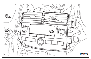
8. REMOVE INTEGRATION CONTROL AND PANEL ASSEMBLY

(a) Remove the 4 screws, and release the integration control & panel assembly.
(b) Disconnect the connectors and remove the integration control & panel assembly.
 Integration control and panel
COMPONENTS
...
 Disassembly
1. REMOVE CENTER CLUSTER MODULE KNOB NO.1 (for Manual Air Conditioning
System)
(a) Remove the center cluster module knob No. 1.
2. REMOVE CENTER CLUSTER MODULE KNOB NO.2 (for Manual Air Condit ...
Other materials:
Disposal
HINT:
When scrapping a vehicle equipped with the SRS or
disposing of the steering pad, be sure to deploy the airbag
first in accordance with the procedure described below. If any
abnormality occurs with airbag deployment, contact the
SERVICE DEPT. of TOYOTA MOTOR SALES, U.S.A., INC.
CAUTION:
...
How to proceed with
troubleshooting
HINT:
Use these procedures to troubleshoot the power door lock
control system.
The intelligent tester should be used in steps 4 and 5.
1 VEHICLE BROUGHT TO WORKSHOP
2 CUSTOMER PROBLEM ANALYSIS CHECK
HINT:
In troubleshooting, confirm that the problem symptoms
have ...
Inspection
1. INSPECT FRONT SEAT INNER BELT ASSEMBLY RH
Release the seat belt (Buckle switch is ON).
Check the resistance between the terminals.
Standard
If the result is not as specified, replace the inner belt
assembly.
Inspect the buckle switch.
Fasten ...
