Toyota Sienna Service Manual: Disassembly
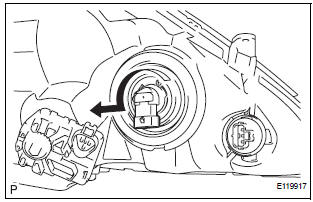
1. REMOVE NO. 1 HEADLIGHT BULB (HALOGEN HEADLIGHT)
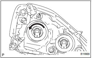
- Turn in the direction indicated by the arrow and remove the No. 1 headlight bulb.
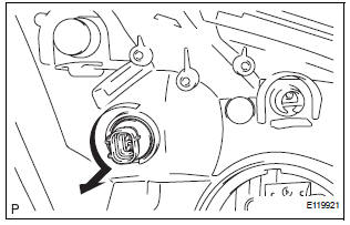
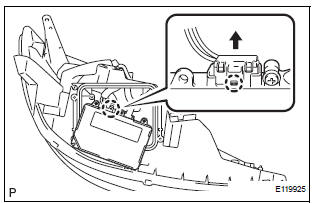
2. REMOVE DISCHARGE HEADLIGHT BULB (DISCHARGE HEADLIGHT)
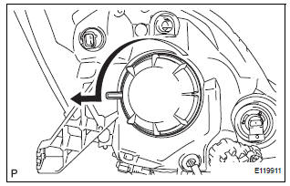
- Turn in the direction indicated by the arrow and disconnect the socket.
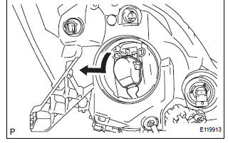
- Release the lock of the set spring and remove the discharge headlight bulb as shown in the illustration.
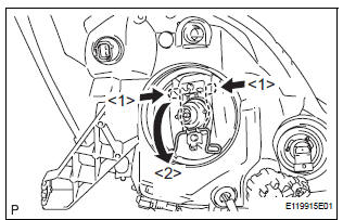
3. REMOVE NO. 2 HEADLIGHT BULB
- Turn in the direction indicated by the arrow and remove the No. 2 headlight bulb.
4. REMOVE FRONT TURN SIGNAL LIGHT BULB
- Turn in the direction indicated by the arrow and remove the front turn signal light bulb and front turn signal light socket as a unit.
- Remove the front turn signal light bulb from the front turn signal light socket.
5. REMOVE FRONT SIDE MARKER LIGHT BULB
- Turn in the direction indicated by the arrow and remove the side marker light bulb and side marker light socket as a unit.
- Remove the side marker light bulb from the side marker light socket.
6. REMOVE LIGHT CONTROL ECU (DISCHARGE HEADLIGHT)
- Remove the 4 screws and headlight cover.
- Remove the headlight gasket.
- Remove the 2 screws.
- Disengage the claw.
- Disconnect the connector and remove the light control ECU.
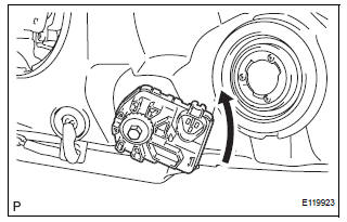
- Remove the headlight leveling motor assembly as shown in the illustration.
- Remove the headlight leveling motor base packing.
 Removal
1. DISCONNECT CABLE FROM NEGATIVE BATTERY
TERMINAL
2. REMOVE FRONT BUMPER ASSEMBLY
3. REMOVE HEADLIGHT ASSEMBLY
Disconnect the connectors.
Remove the bolt, 3 screws and headligh ...
 Adjustment
1. VEHICLE PREPARATION FOR HEADLIGHT AIMING
ADJUSTMENT
Prepare the vehicle:
Ensure there is no damage or deformation to the
body around the headlights.
Fill the fuel t ...
Other materials:
Diagnostic trouble code chart
HINT:
The parameters listed in the chart may not confirm exactly to
those read during the DTC check due to the type of
instrument or other factors.
If a trouble code is displayed during the DTC check in the
check mode, check the circuit for the code listed in the table
below. For details of ...
Evaporative Emission Control System Pressure
DTC P0450 Evaporative Emission Control System Pressure
Sensor / Switch
DTC P0451 Evaporative Emission Control System Pressure
Sensor Range / Performance
DTC P0452 Evaporative Emission Control System Pressure
Sensor / Switch Low Input
DTC P0453 Evaporative Emission Control System Pressure
Sens ...
Back-up Power Source Circuit
DESCRIPTION
This is the back-up power source for the A/C amplifier. Power is supplied
even when the ignition switch is
off and is used for diagnostic trouble code memory, etc.
WIRING DIAGRAM
INSPECTION PROCEDURE
1 INSPECT FUSE (ECU-B)
(a) Remove the ECU-B fuse from the engine room juncti ...
