Toyota Sienna Service Manual: Removal
HINT: On the RH side, use the same procedures as on the LH side.
1. REMOVE SLIDE DOOR
- Remove the rear door scuff plate (See page IR-7).
- Remove the back door scuff plate (See page ED- 214).
- Remove the quarter trim panel (See page IR-9).
- Remove the upper rail cushion from the rail.
- Disconnect the 2 connectors from the body side and remove the bolt and wire.
- Open the quarter glass.
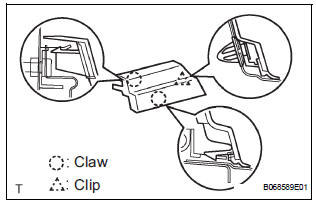
- Using a screwdriver, disengage the clip and 2 claws, remove the rail end moulding.
HINT: Tape the screwdriver tip before use.
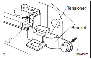
- Remove the 2 bolts and bracket center No. 2 together with the tensioner (color: white).
- Remove the tensioner from the bracket center No.
2.
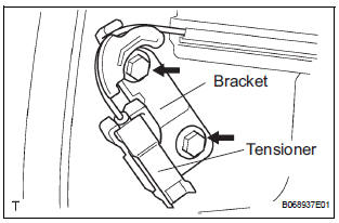
- Remove the 2 bolts and bracket center No. 1 together with the tensioner (color: black).
- Remove the tensioner from the bracket center No.
1.
- Remove the 2 nuts and open stop.
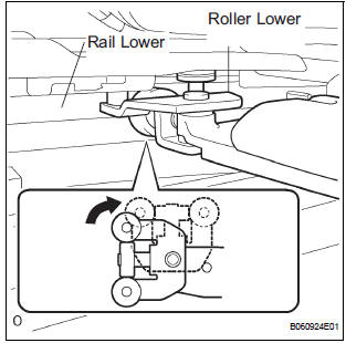
- Rotate the base of the slide door roller lower in the direction indicated by arrow in the illustration and then remove the roller from the cut area of the lower rail from the body side.
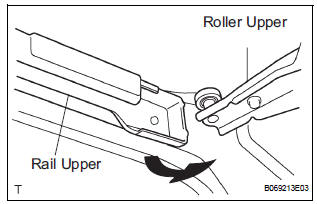
- Move the slide door rearward and then remove the slide door roller upper from the cut area in the rear part of the slide door rail upper.
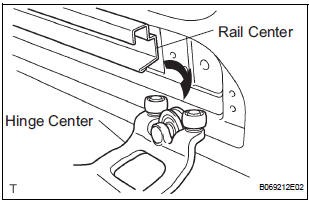
- Move the slide door further rearward and then remove the slide door hinge center from the rear part of the slide door rail center. Then, remove the slide door.
2. REMOVE SLIDE DOOR RAILS
- Remove the roof headlining (See page IR-6).
- Remove the 2 bolts, 2 nuts and the rail upper.
- Remove the 2 screws and rear side rail.
- Remove the 3 screws and rail center
3. REMOVE SLIDE DOOR FULL OPEN STOP LOCK ASSEMBLY LH
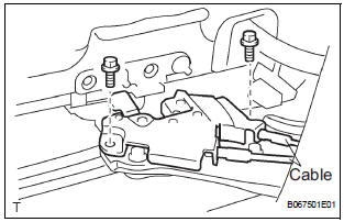
- Disconnect the 2 cables.
- Remove the 2 bolts and full open stop lock.
4. REMOVE SLIDE DOOR ROLLER ASSEMBLY LOWER LH
- Remove the 3 bolts and roller.
5. REMOVE SLIDE DOOR HINGE ASSEMBLY CENTER LH
- Remove the 3 bolts and hinge.
- LH side: Remove the cover.
6. REMOVE SLIDE DOOR ROLLER ASSEMBLY UPPER
- Remove the 2 bolts and roller.
 Power slide door
COMPONENTS
...
 Disassembly
1. REMOVE REAR DOOR WINDOW FRAME MOULDING
REAR LH (See page ET-31)
2. REMOVE REAR DOOR WINDOW FRAME MOULDING
SUB-ASSEMBLY LH (See page ET-32)
3. REMOVE SLIDE DOOR WINDOW GARNISH LH
Fully o ...
Other materials:
Camshaft Position "A" - Timing Over-Advanced
DTC P0011 Camshaft Position "A" - Timing Over-Advanced
or System Performance (Bank 1)
DTC P0012 Camshaft Position "A" - Timing Over-Retarded
(Bank 1)
DTC P0021 Camshaft Position "A" - Timing Over-Advanced
or System Performance (Bank 2)
DTC P0022 Camshaft Position ...
Inspection
1. INSPECT HEATED OXYGEN SENSOR (for Bank 1
Sensor 2)
(a) Measure the resistance of the sensor.
Standard resistance
If the resistance is not as specified, replace the
sensor.
2. INSPECT HEATED OXYGEN SENSOR (for Bank 2
Sensor 2)
(a) Measure the resistance of the sensor.
Standard r ...
Removal
1. REMOVE BACK DOOR CENTER GARNISH
Using a clip remover, disengage the 5 clips to
remove the back door center garnish.
2. REMOVE REAR SPOILER
Disconnect the center stop light connector.
Remove the 3 nuts.
Using a clip remover, disengage the 2 clips to
remove the rear s ...
