Toyota Sienna Service Manual: Rear Air Outlet Damper Position Sensor Circuit
DESCRIPTION
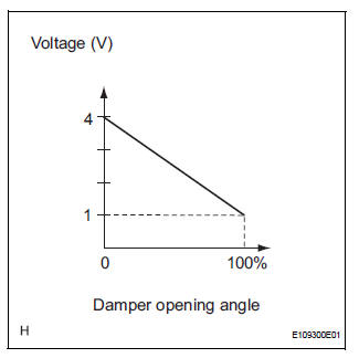
This sensor detects the position of the rear air outlet control servo motor and sends the appropriate signals to the A/C amplifier. The position sensor is built in the rear air outlet control servo motor.
The position sensor's resistance changes as the rear air outlet control servo motor arm moves.
It outputs voltage (5 V) that is input to terminal 2 and terminal 3 via the variable resister, and then to the A/ C amplifier.
The A/C amplifier determines the arm position based on the input voltage from
the position sensor.
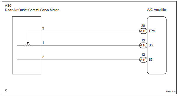
WIRING DIAGRAM
INSPECTION PROCEDURE
1 READ VALUE OF INTELLIGENT TESTER
(a) Connect the intelligent tester to the DLC3.
(b) Turn the ignition switch to the ON position and turn the intelligent tester main switch on.
(c) Select the items below in the DATA LIST, and read the display on the intelligent tester.
DATA LIST / AIR CONDITIONER 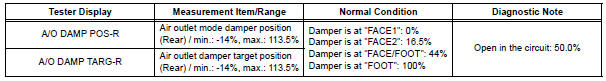
OK: The display is as specified in the normal condition column.
Result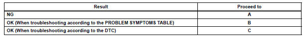

2 INSPECT REAR AIR OUTLET CONTROL SERVO MOTOR
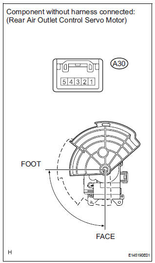
(a) Remove the rear air outlet control servo motor.
(b) Disconnect the connector from the rear air outlet control servo motor.
(c) Measure the resistance according to the value(s) in the table below.
Standard resistance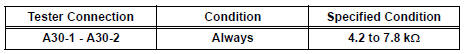
(d) Measure the resistance according to the value(s) in the table below.
Standard resistance 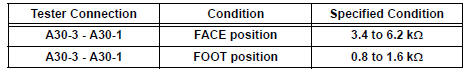
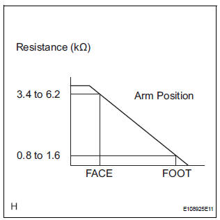
(e) As the rear air outlet control servo motor moves from FACE to FOOT, the resistance decreases gradually without interruption.
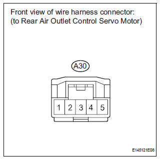
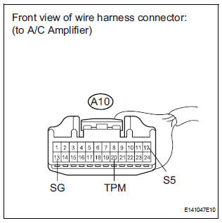
3 CHECK HARNESS AND CONNECTOR (REAR AIR OUTLET CONTROL SERVO MOTOR - A/C AMPLIFIER)
(a) Disconnect the connector from the A/C amplifier.
(b) Measure the resistance according to the value(s) in the table below.
Standard resistance 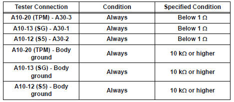

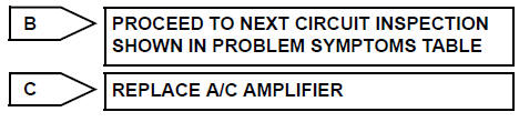
REPLACE A/C AMPLIFIER
 Rear Air Mix Damper Position Sensor Circuit
DESCRIPTION
This sensor detects the position of the rear air mix control servo motor
(water valve servo motor) and
sends the appropriate signals to the A/C amplifier. The position sensor is bu ...
 Air Mix Damper Control Servo Motor Circuit (Passenger Side)
DESCRIPTION
The air mix control servo motor (air mix damper servo sub-assembly) is
controlled by the A/C amplifier.
The air mix control servo motor moves the air mix damper by rotating (normal, ...
Other materials:
Vehicle Speed Sensor Malfunction
DTC P0500 Vehicle Speed Sensor Malfunction
DTC P0503 Vehicle Speed Sensor Circuit Malfunction
DESCRIPTION
The cruise control system uses the same vehicle speed signal that is sent to
the ECM for the SFI system.
If DTC P0500 is detected, perform the diagnosis using the inspection procedure
...
TC and CG Terminal Circuit
DESCRIPTION
DTC output mode is set by connecting terminals 13 (TC) and 4 (CG) of the
DLC3. The DTCs are indicated
by blinks of the tire pressure warning light.
WIRING DIAGRAM
HINT:
When each warning light blinks continuously, a ground short in the wiring of
terminal TC of the DLC3 or an ...
Disassembly
1. REMOVE FRONT DIFFERENTIAL RING GEAR
(a) Place the match-marks on the ring gear and
differential case.
(b) Remove the 16 bolts.
(c) Using a plastic hammer, tap ring gear to remove it
from the case.
2. REMOVE FRONT DIFFERENTIAL SIDE GEAR
(a) Remove the differential LH case fr ...
