Toyota Sienna Service Manual: Disassembly
1. Remove park/neutral position switch assembly
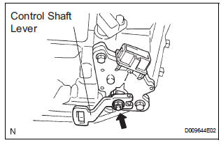
(A) remove the nut, washer and control shaft lever.
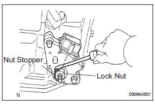
(B) using a screwdriver, unstake the nut stopper, and remove the lock nut and nut stopper.
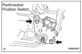
(c) Remove the 2 bolts and pull out the park/neutral position switch.
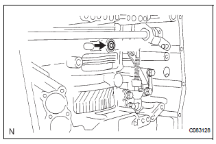
2. REMOVE BREATHER PLUG HOSE
(a) Remove the breather plug hose from the transaxle case.
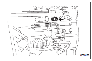
3. REMOVE OIL COOLER TUBE UNION (INLET OIL COOLER UNION)
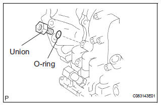
(a) Remove the union.
(b) Remove the O-ring from the union.
4. REMOVE OIL COOLER TUBE UNION (OUTLET OIL COOLER UNION)
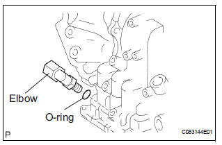
(a) Remove the elbow.
(b) Remove the O-ring from the elbow.
5. REMOVE SPEED SENSOR
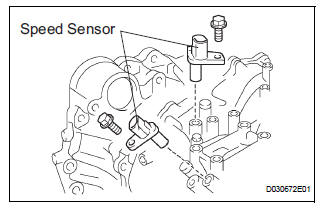
(a) Remove the 2 bolts and the 2 speed sensors from the transaxle assembly.
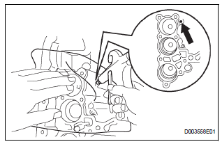
6. REMOVE TRANSAXLE CASE NO.1 PLUG
(a) Remove the 4 transaxle case No.1 plugs from the transaxle case.
(b) Remove the 4 O-rings from the 4 transaxle case No.1 plugs.
7. FIX AUTOMATIC TRANSAXLE ASSEMBLY
(a) Fix the transaxle assembly.
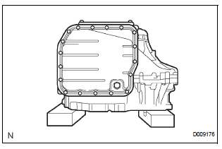
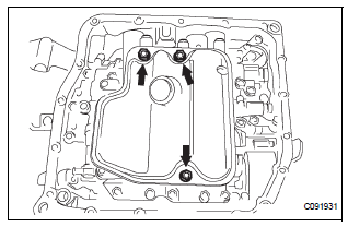
8. REMOVE AUTOMATIC TRANSAXLE OIL PAN SUBASSEMBLY
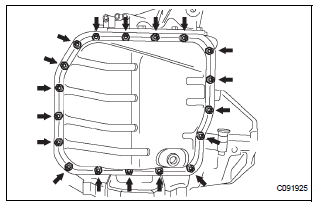
(a) Remove the 18 bolts, oil pan and gasket.
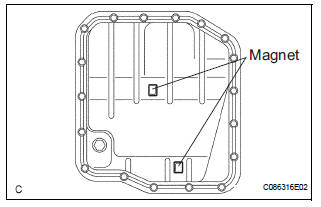
(b) Remove the 2 magnets from the oil pan.
9. INSPECT TRANSMISSION OIL CLEANER MAGNET
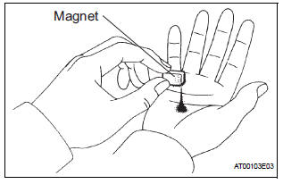
(a) Remove the magnets and use them to collect any steel chips. Examine the chips and particles in the pan and on the magnet to determine what type of wear has occurred in the transaxle:
Result: Steel (magnetic): Wear of the bearing, gear and plate Brass (non-magnetic): Wear of the bushing
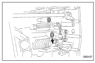
10. DISCONNECT TRANSMISSION WIRE

(a) Remove the 7 connectors from the shift solenoid valves.
(b) Remove the bolt, lock plate and temperature sensor.
11. REMOVE TRANSMISSION WIRE
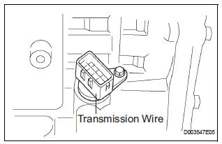
(a) Remove the bolt and transmission wire from the transaxle case.
12. REMOVE VALVE BODY OIL STRAINER ASSEMBLY
(a) Remove the 3 bolts and oil strainer.
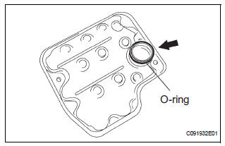
(b) Remove the O-ring from the oil strainer.
13. REMOVE TRANSMISSION VALVE BODY ASSEMBLY
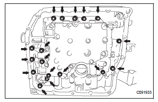
(a) Support the valve body assembly and remove the 17 bolts and valve body assembly.
14. REMOVE GOVERNOR APPLY GASKET NO.1
(a) Remove the governor apply gasket No.1 from the transaxle case.
15. REMOVE TRANSAXLE CASE 2ND BRAKE GASKET
(a) Remove the transaxle case 2nd brake gasket from the transaxle case.
16. REMOVE BRAKE DRUM GASKET
(a) Remove the brake drum gasket from the transaxle case.
17. REMOVE CHECK BALL BODY
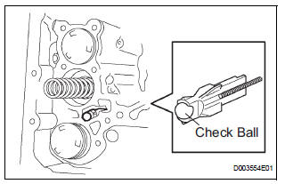
(a) Remove the check ball body and spring from the transaxle case.
18. REMOVE C-3 ACCUMULATOR PISTON
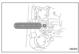
(a) Remove the spring from the C-3 accumulator piston.
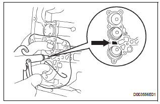
(b) Apply compressed air (392 kPa, 4.0 kgf/cm2, 57 psi) to the oil hole and remove the C-3 accumulator piston.
NOTICE:
|
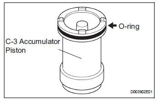
(c) Remove the O-ring from the C-3 accumulator piston.
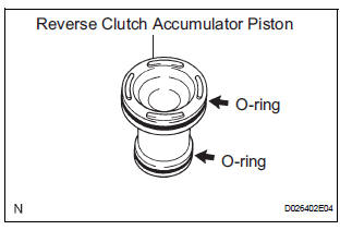
19. REMOVE REVERSE CLUTCH ACCUMULATOR PISTON
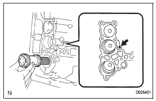
(a) Apply compressed air (392 kPa, 4.0 kgf/cm2, 57 psi) to the oil hole and remove the reverse accumulator piston and spring.
NOTICE:
|
(b) Remove the 2 O-rings from the reverse clutch accumulator piston.
20. REMOVE B-3 ACCUMULATOR PISTON
(a) Apply compressed air (392 kPa, 4.0 kgf/cm2, 57 psi) to the oil hole and remove the B-3 accumulator piston and 2 springs.
NOTICE:
|
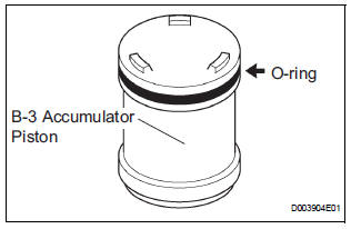
(b) Remove the O-ring from the B-3 accumulator piston.
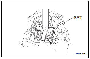
21. REMOVE MANUAL VALVE LEVER SHAFT RETAINER SPRING
(a) Using needle-nose pliers, remove the manual valve lever shaft retainer spring.
22. REMOVE MANUAL DETENT SPRING SUBASSEMBLY
(a) Remove the 2 bolts, the manual detent spring subassembly and cover.
24. REMOVE MANUAL VALVE LEVER SUB-ASSEMBLY
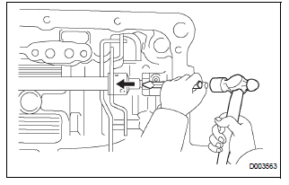
(a) Using a chisel and hammer, cut off and remove the spacer.
(b) Using a pin punch (φ35 mm) and hammer, drive out the pin.
HINT: Slowly drive out the pin so that it will not fall into the transaxle case.
(c) Remove the manual valve lever shaft and manual valve lever.
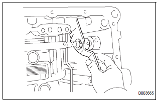
25. REMOVE PARKING LOCK ROD SUB-ASSEMBLY
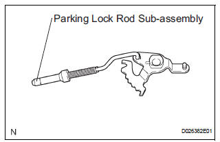
(a) Remove the parking lock rod from the manual valve lever.
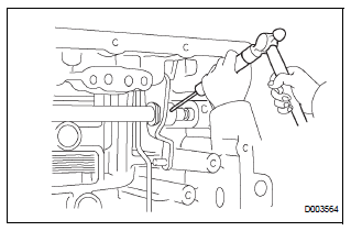
26. REMOVE MANUAL VALVE LEVER SHAFT OIL SEAL
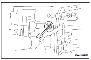
(a) Using a screwdriver, remove the oil seal from the transaxle case.
| NOTICE: Do not apply excessive force when removing the oil seal. |
27. FIX AUTOMATIC TRANSAXLE ASSEMBLY
(a) Fix the transaxle case with the oil pump side facing up.
28. INSPECT INPUT SHAFT ENDPLAY
HINT: (See page AX-200)
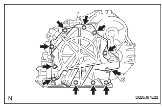
29. REMOVE TRANSAXLE HOUSING
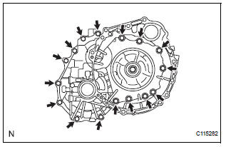
(a) Remove the 16 bolts.
(b) Tap on the circumference of the transaxle housing with a plastic hammer to remove the transaxle housing from the transaxle case.
| NOTICE: The differential may be accidentally removed when the transaxle housing is removed. |
30. REMOVE OIL PUMP ASSEMBLY
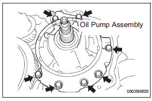
(a) Remove the 7 bolts and oil pump from the transaxle case.
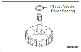
31. REMOVE THRUST NEEDLE ROLLER BEARING
(a) Remove the thrust needle roller bearing from the underdrive planetary gear assembly.
32. REMOVE THRUST BEARING UNDERDRIVE RACE NO.2
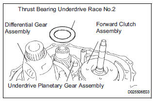
(a) Remove the thrust bearing underdrive race No.2 from the underdrive planetary gear assembly.
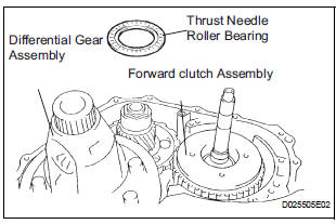
33. REMOVE DIFFERENTIAL GEAR ASSEMBLY
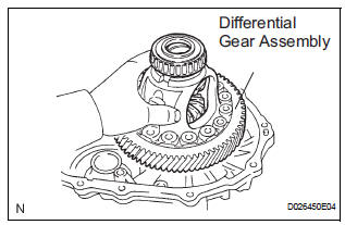
(a) Remove the differential gear assembly from the transaxle case.
34. REMOVE OVERDRIVE BRAKE GASKET
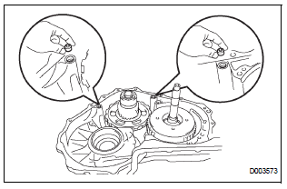
(a) Remove the 2 overdrive brake gaskets from the transaxle case.
35. REMOVE FORWARD CLUTCH ASSEMBLY
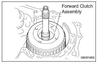
(a) Remove the forward clutch assembly from the transaxle case.
(b) Remove the thrust needle roller bearing from the forward clutch.
36. REMOVE MULTIPLE DISC CLUTCH HUB
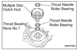
(a) Remove the thrust needle roller bearing, multiple disc clutch hub, thrust needle roller bearing and thrust bearing race No.1 from the transaxle case.
37. INSPECT MULTIPLE DISC CLUTCH CLUTCH HUB
HINT: (See page AX-197)
38. REMOVE UNDERDRIVE PLANETARY GEAR ASSEMBLY
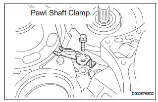
(a) Remove the bolt and pawl shaft clamp.
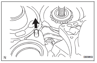
(b) Remove the parking lock pawl shaft.
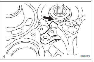
(c) Push the parking lock pawl.
HINT: Failure to do so will cause interference when the underdrive planetary gear is removed.
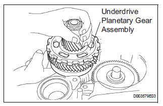
(d) Remove the underdrive planetary gear assembly from the transaxle case.
| NOTICE: Be careful so that the underdrive planetary gear assembly will not fall out. |
39. REMOVE PARKING LOCK PAWL
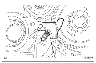
(a) Remove the spring, pawl pin and parking lock pawl.
40. REMOVE UNDERDRIVE CLUTCH ASSEMBLY
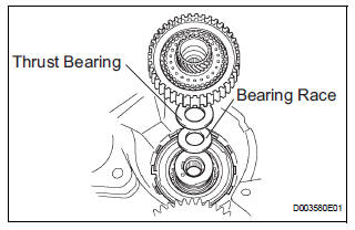
(a) Remove the underdrive clutch assembly, thrust bearing and bearing race from the transaxle case.
41. REMOVE UNDERDRIVE 1-WAY CLUTCH ASSEMBLY
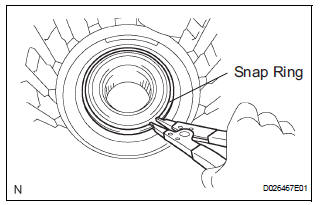
(a) Using a screwdriver, remove the snap ring from the transaxle case.
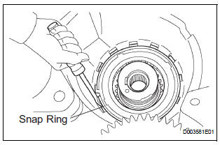
| NOTICE: Do not apply excessive force when removing the snap ring. |
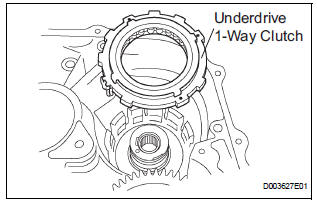
(b) Remove the underdrive 1-way clutch from the transaxle case.
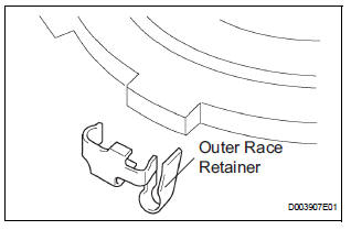
(c) Remove the outer race retainer from the 1-way clutch.
42. REMOVE UNDERDRIVE CLUTCH DISC NO.2
(a) Using a screwdriver, remove the snap ring.
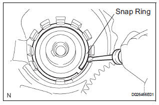
| NOTICE: Do not apply excessive force when removing the snap ring. |
(b) Remove the flange, 4 discs and 4 plates from the transaxle case.
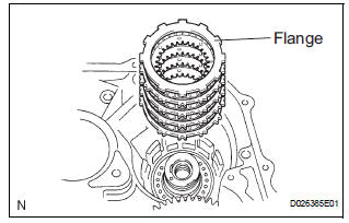
43. INSPECT UNDERDRIVE CLUTCH DISC NO.2
HINT: (See page AX-197)
44. REMOVE TRANSAXLE REAR COVER SUBASSEMBLY
(a) Remove the 11 bolts.
(b) Tap on the circumference of the rear cover with a plastic hammer to remove the transaxle rear cover from the transaxle case.
45. REMOVE TRANSAXLE CASE NO.1 PLUG
(a) Remove the 4 transaxle case No.1 plugs from the transaxle rear cover.
(b) Remove the 4 O-rings from the 4 transaxle case No.1 plugs.
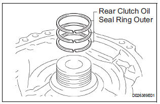
46. REMOVE REAR CLUTCH OIL SEAL RING OUTER
47. REMOVE NEEDLE-ROLLER BEARING
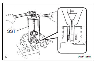
(a) Using SST, remove the needle-roller bearing from the transaxle rear cover.
SST 09387-00041 (09387-01021, 09387-01030, 09387-01040)
48. REMOVE GOVERNOR APPLY GASKET NO.1
(a) Using a screwdriver, remove the 3 apply gaskets.
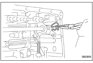
49. REMOVE BRAKE APPLY TUBE
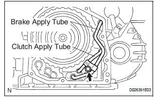
(a) Remove the bolt, clamp and brake apply tube.
(b) Remove the clutch apply tube.
(c) Remove the brake apply tube from the clamp.
| NOTICE: Do not bend the tubes. |
50. REMOVE DIRECT CLUTCH ASSEMBLY
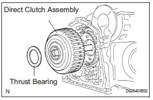
(a) Remove the thrust bearing and the direct clutch assembly from the transaxle case.
51. REMOVE OVERDRIVE DIRECT CLUTCH HUB SUBASSEMBLY
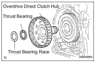
(a) Remove the thrust bearing race, thrust bearing and overdrive direct clutch hub from the planetary gear assembly.
52. INSPECT OVERDRIVE DIRECT CLUTCH DRUM SUBASSEMBLY
HINT: (See page AX-198)
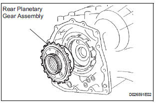
53. REMOVE REAR PLANETARY SUN GEAR ASSEMBLY
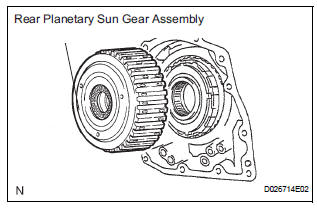
(a) Remove the rear planetary sun gear assembly from the transaxle case.
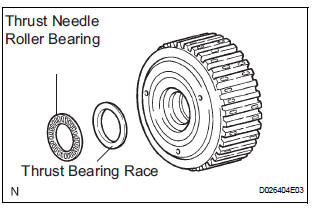
(b) Remove the thrust needle roller bearing and thrust bearing race from the rear planetary sun gear assembly.
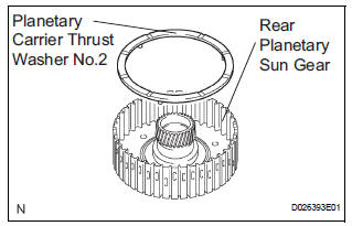
(c) Remove the planetary carrier thrust washer No.2 from the rear planetary sun gear assembly.
54. REMOVE 1-WAY CLUTCH ASSEMBLY
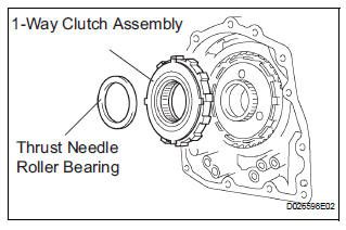
(a) Remove the 1-way clutch assembly and the thrust needle roller bearing from the transaxle case.
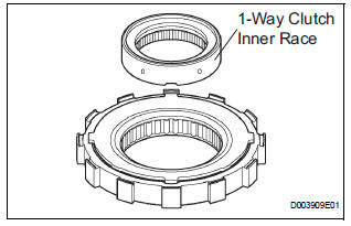
(b) Remove the 1-way clutch inner race from the 1-way clutch assembly.
55. REMOVE 1-WAY CLUTCH SLEEVE OUTER
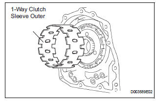
(a) Remove the 1-way clutch sleeve outer from the transaxle case.
56. REMOVE PLANETARY CARRIER THRUST WASHER NO.1
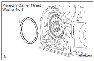
(a) Remove the planetary carrier thrust washer No.1 from the planetary gear assembly.
57. REMOVE 2ND BRAKE CLUTCH DISC
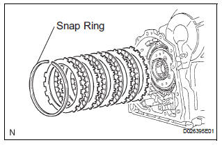
(a) Using a screwdriver, remove the snap ring.
(b) Remove the flange, 4 discs and 4 plates from the transaxle case.
58. INSPECT 2ND BRAKE CLUTCH DISC
HINT: (See page AX-198)
59. REMOVE 2ND BRAKE PISTON ASSEMBLY
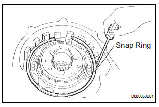
(a) Using a screwdriver, remove the snap ring.
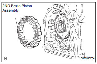
(b) Remove the 2ND brake piston assembly from the transaxle case.
60. REMOVE REAR PLANETARY GEAR ASSEMBLY
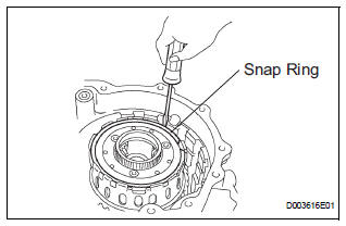
(a) Using a screwdriver, remove the snap ring.
(b) Remove the rear planetary gear assembly from the transaxle case.
61. REMOVE INPUT SUN GEAR
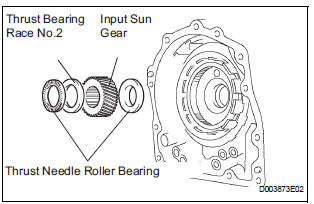
(a) Remove the 2 thrust needle roller bearings, thrust bearing race No.2 and the input sun gear from the transaxle case.
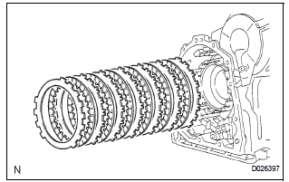
62. REMOVE 1ST AND REVERSE BRAKE CLUTCH DISC
(a) Remove the flange, 6 discs and 6 plates from the transaxle case.
63. INSPECT 1ST AND REVERSE BRAKE CLUTCH DISC
HINT: (See page AX-198)
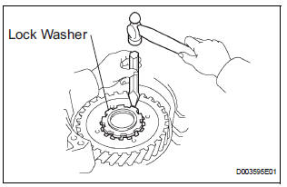
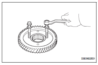
64. REMOVE FRONT PLANETARY GEAR ASSEMBLY
(a) Using a chisel and hammer, unstake the lock washer.
| NOTICE: Push down all claws of the washer. Otherwise the SST cannot be fully pressed against the nut, and cannot loosen the nut. |
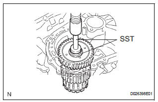
(b) Using SST, remove the nut.
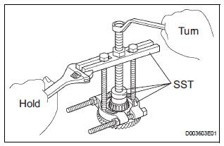
SST 09387-00030, 09387-00080
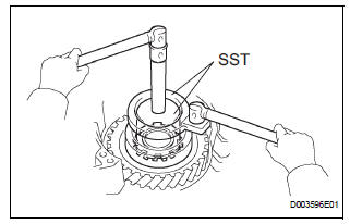
(c) Using SST and a press, remove the front planetary gear assembly from the counter drive gear.
SST 09950-60010 (09951-00450), 09950-70010 (09951-07100)
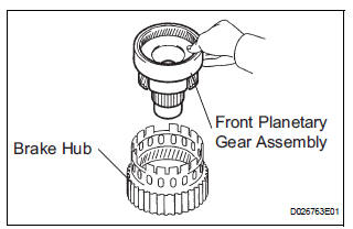
(d) Remove the front planetary gear assembly from the brake hub.
65. REMOVE FRONT PLANETARY RING GEAR
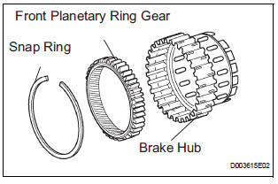
(a) Using a screwdriver, remove the snap ring and front planetary ring gear from the brake hub.
66. REMOVE 1ST AND REVERSE BRAKE RETURN SPRING SUB-ASSEMBLY
(a) Place SST on the return spring, and compress the return spring with a press.
SST 09387-00070
(b) Using a snap ring expander, remove the snap ring.
NOTICE:
|
67. INSPECT 1ST AND REVERSE BRAKE RETURN SPRING SUB-ASSEMBLY
HINT: (See page AX-198)
68. REMOVE 1ST AND REVERSE BRAKE PISTON
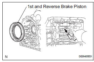
(a) Apply compressed air (392 kPa, 4.0 kgf/cm2, 57 psi) to the transaxle case to remove the 1st and reverse brake piston.
NOTICE:
|
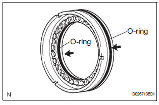
(b) Remove the 2 O-rings from the 1st and reverse brake piston.
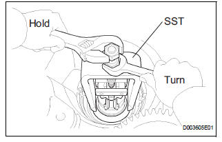
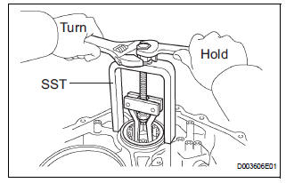
69. REMOVE COUNTER DRIVE GEAR
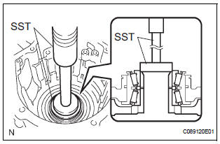
(a) Using SST and a press, remove the counter drive gear from the transaxle case.
SST 09950-60010 (09951-00590), 09950-70010 (09951-07100)
(b) As shown in the illustration, tighten the 2 bolts evenly and make clearance of approx. 20.0 mm (0.787 in.) between the counter drive gear and the inner race.
(c) Using SST, remove the tapered roller bearing.
SST 09950-60010 (09951-00590), 09950-00020, 09950-00030, 09950-40011 (09957-04010)
70. REMOVE TRANSFER DRIVEN PINION FRONT BEARING
(a) Using a snap ring expander, remove the snap ring.
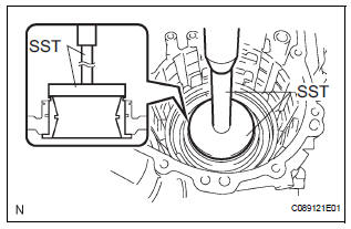
(b) Using SST and a press, remove the bearing outer race.
SST 09950-60020 (09951-00910)
71. REMOVE BREATHER PLUG NO.2 (ATM)
72. REMOVE UNDERDRIVE BRAKE RETURN SPRING SUB-ASSEMBLY
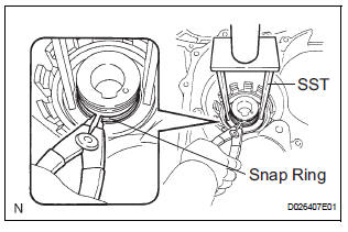
(a) Place SST on the return spring, and compress the return spring with a press.
SST 09387-00020
(b) Using a snap ring expander, remove the snap ring.
NOTICE:
|
73. INSPECT UNDERDRIVE BRAKE RETURN SPRING SUB-ASSEMBLY
HINT: (See page AX-199)
74. REMOVE UNDERDRIVE BRAKE PISTON
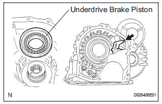
(a) Apply compressed air (392 kPa, 4.0 kgf/cm2, 57 psi) to the transaxle case to remove the underdrive brake piston.
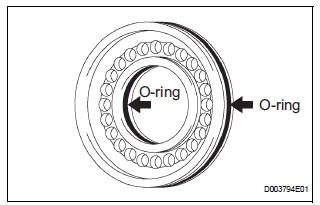
(b) Remove the 2 O-rings from the underdrive brake piston.
75. REMOVE NEEDLE ROLLER BEARING
(a) Using SST, remove the needleroller bearing from the transaxle case.
SST 09387-00041 (09387-01010, 09387-01030, 09387-01040)
76. REMOVE UNDERDRIVE CLUTCH DRUM OIL SEAL RING
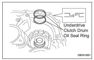
(a) Remove the 2 oil seal rings from the transaxle case.
77. REMOVE TRANSAXLE CASE NO.1 PLUG
(a) Remove the 2 transaxle case No.1 plugs.
(b) Remove the 2 O-rings from the 2 transaxle case No.1 plugs.
78. REMOVE UNDERDRIVE CYLINDRICAL ROLLER BEARING
(a) Using SST, remove the underdrive cylindrical roller bearing from the transaxle case.
SST 09514-35011
79. REMOVE UNDERDRIVE OUTPUT SHAFT OIL SEAL RING
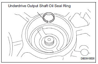
(a) Remove the oil seal ring from the transaxle housing.
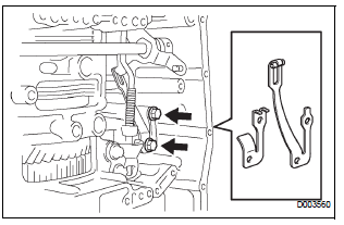
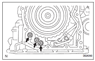
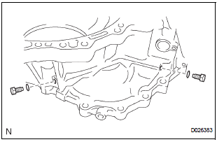
80. REMOVE DIFFERENTIAL GEAR LUBE APPLY TUBE
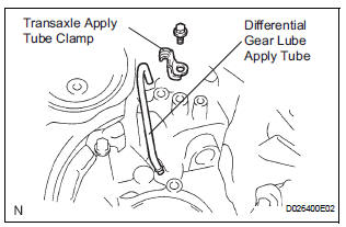
(a) Remove the bolt, transaxle apply tube clamp and differential gear lube apply tube from the transaxle housing.
| NOTICE: Do not bend the tubes. |
 Automatic transaxle unit
COMPONENTS
...
 Inspection
1. INSPECT MULTIPLE DISC CLUTCH HUB
(a) Using a dial indicator, measure the inside diameter
of the forward clutch hub bushing
Standard inside diameter:
23.025 to 23.046 mm (0.9065 to 0.9073 in ...
Other materials:
Installation
1. INSTALL FRONT STABILIZER BAR
2. INSTALL NO. 1 FRONT STABILIZER BAR BUSHING
(a) Install the 2 front stabilizer bar bush No.1 to the
stabilizer bar front.
NOTICE:
Install the bushings with the slit facing on the
rear side of the vehicle.
HINT:
Install the bushing to the outer side of th ...
Refrigerant
On-vehicle inspection
1. INSPECT REFRIGERANT PRESSURE WITH MANIFOLD GAUGE SET
(a) This method uses a manifold gauge set to locate
problem areas. Read the manifold gauge pressure
when these conditions are established.
Test conditions:
Temperature at the air inlet is 30 to 35°C (86 to
95 ...
Stereo Component Amplifier Power Source Circuit
DESCRIPTION
This circuit provides power to the stereo component amplifier.
WIRING DIAGRAM
INSPECTION PROCEDURE
1 INSPECT STEREO COMPONENT AMPLIFIER
Disconnect the stereo component amplifier connectors.
Measure the resistance according to the values in the
table below.
Standard ...
