Toyota Sienna Service Manual: Installation
1. INSTALL STEERING COLUMN ASSEMBLY
(a) Install the steering column assembly with the 3 bolts.
Torque: 25 N*m (255 kgf*cm, 18 ft.*lbf) (b) Connect the connectors.
(c) Connect the wire harness clamps to the steering column tube.
2. CONNECT STEERING INTERMEDIATE SHAFT ASSEMBLY
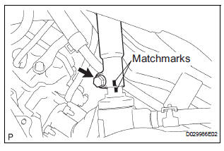
(a) Align the matchmarks on the intermediate shaft assembly and steering gear assembly.
(b) Install the steering intermediate shaft assembly with the bolt.
Torque: 36 N*m (370 kgf*cm, 27 ft.*lbf)
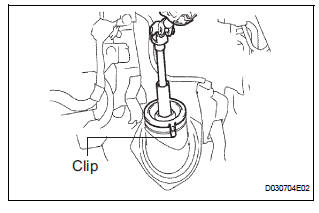
(c) Install the dust cover to the hole cover. Check that the 3 clips of the dust cover are securely fitted into the groove on the hole cover.
3. PLACE FRONT WHEELS FACING STRAIGHT AHEAD
4. INSTALL SPIRAL CABLE SUB-ASSEMBLY (See page RS-434)
5. INSTALL STEERING COLUMN COVER
6. CENTER SPIRAL CABLE (See page RS-435)
7. INSTALL STEERING WHEEL ASSEMBLY
(a) Align the matchmarks on the steering wheel assembly and steering main shaft assembly.
(b) Install the steering wheel assembly set nut.
Torque: 50 N*m (510 kgf*cm, 37 ft.*lbf) (c) Connect the connector.
8. INSPECT STEERING WHEEL CENTER POINT
9. INSPECT HORN BUTTON ASSEMBLY (See page RS- 425)
10. INSTALL HORN BUTTON ASSEMBLY (See page RS- 424)
11. INSTALL STEERING WHEEL COVER LOWER NO.3 (See page RS-425)
12. INSTALL STEERING WHEEL COVER LOWER NO.2 (See page RS-425)
13. CONNECT BATTERY NEGATIVE TERMINAL
14. INSPECT SRS WARNING LIGHT (See page RS-436)
 Reassembly
1. INSTALL IGNITION OR STARTER SWITCH
ASSEMBLY
(a) Install the ignition or starter switch assembly to the
steering column bracket assembly UPR with the 2
screws.
2. INSTALL KEY INTER LOCK SOLENOI ...
 Power steering
...
Other materials:
Removal
HINT:
On the RH side, use the same procedures as on the LH side.
1. REMOVE BACK DOOR STAY SUB-ASSEMBLY LH
Remove the 2 bolts and disconnect the stay from
the body panel.
Using the screwdriver, disengage the clips and
remove the stay from the door panel.
Remove the bolt from door pa ...
Vehicle interior
Items
Check points
Accelerator pedal
The accelerator pedal should move
smoothly (without uneven pedal effort or
catching).
Automatic transaxle “Park”
mechanism
When parked on a slope with the shift
lever in P, is ...
Removal
1. DISCONNECT CABLE FROM NEGATIVE BATTERY
TERMINAL
CAUTION: Wait for 90 seconds after disconnecting the cable
to prevent the airbag working.
2. REMOVE INSTRUMENT CLUSTER FINISH PANEL SUB-ASSEMBLY
Disengage the 4 clips and remove the instrument
cluster finish panel sub-assembly.
...
