Toyota Sienna Service Manual: Disassembly
1. REMOVE FRONT DIFFERENTIAL RING GEAR
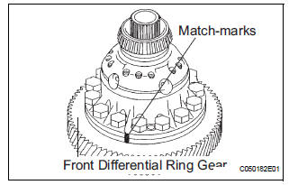
(a) Place the match-marks on the ring gear and differential case.
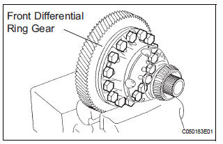
(b) Remove the 16 bolts.
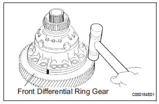
(c) Using a plastic hammer, tap ring gear to remove it from the case.
2. REMOVE FRONT DIFFERENTIAL SIDE GEAR
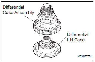
(a) Remove the differential LH case from the differential case assembly.
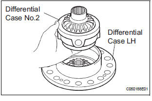
(b) Remove the differential case No.2 from the differential case LH.
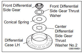
(c) Remove the front differential side gear, front differential side gear thrust washer, conical spring and center differential side gear thrust washer No.2 from the differential case LH.
(d) Using a snap ring expander, remove the pinion shaft spacer snap ring.
(e) Using a pin punch and hammer, remove 3 straight pins.
(f) Remove the center differential pinion shaft and 2 differential pinion shafts.
(g) Remove 4 front differential pinions, 4 front differential pinion thrust washers, front differential pinion shaft holder, front differential planetary ring and differential side gear thrust washer No.1.
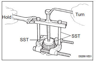
3. REMOVE FRONT DIFFERENTIAL CASE REAR TAPERED ROLLER BEARING
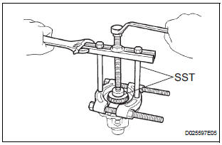
(a) Using SST, remove the front differential case rear tapered roller bearing from the differential case.
SST 09950-00020, 09950-00030, 09950-60010 (09951-00480)
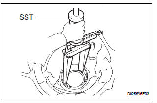
(b) Using SST, remove the front differential case rear tapered roller bearing outer race and differential case washer
SST 09308-00010
4. REMOVE CENTER DIFFERENTIAL PINION
(a) Using torx socket (T50), remove the 15 bolts.
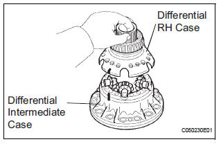
(b) Place the matchmarks on the differential intermediate case and differential case.
(c) Remove the differential intermediate case from the differential case RH.
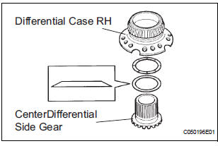
(d) Remove the center differential side gear, conical spring washer and center differential side gear thrust washer No.1 RH from the differential case RH.
(e) Remove the differential spider, 5 center differential pinions and 5 center differential pinion thrust washers from the differential intermediate case.
5. REMOVE FRONT DIFFERENTIAL CASE FRONT TAPERED ROLLER BEARING
(a) Using SST, remove the front differential case front tapered roller bearing from the differential case.
SST 09950-00020, 09950-00030 SST 09950-60010 (09951-00600)
(b) Using SST, remove the front differential case front tapered roller bearing outer race and differential case washer.
SST 09308-00010
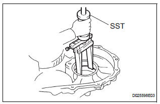
6. REMOVE TRANSAXLE HOUSING OIL SEAL
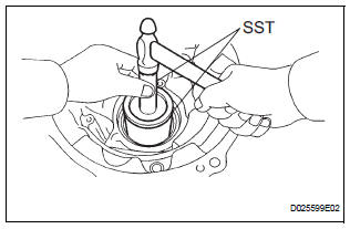
(a) Using SST, remove the oil seal.
SST 09950-70010 (09951-07100) SST 09649-17010
7. REMOVE DIFFERENTIAL SIDE BEARING RETAINER OIL SEAL
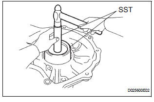
(a) Using SST, remove the oil seal.
SST 09950-70010 (09951-07100), 09608-10010
 Differential case
COMPONENTS
...
 Inspection
1. INSPECT FRONT DIFFERENTIAL
(a) Using a dial indicator, measure the backlash of one
pinion gear while holding the front differential side
gear toward the case.
Standard backlash:
0.05 - 0.2 ...
Other materials:
Removal
1. Disconnect battery negative terminal
2. Remove instrument cluster finish panel
sub-assembly center
Hint:
(see page ip-9)
3. Remove transmission control cable assembly
(a) Remove the nut from the control shaft lever.
(b) Disconnect the transmission control cable assembly
from the con ...
Setting up intuitive parking assist
You can change the buzzer sound volume and the screen operating
conditions.
Press the “APPS” button.
Select “Setup” on the screen.
Select “Vehicle” on the screen.
Select “TOYOTA Park Assist Settings” on the screen.
Select the desired item.
The buzzer sound volu ...
Short to GND in Curtain Shield Squib RH Circuit
DTC B1162/81 Short to GND in Curtain Shield Squib RH Circuit
DESCRIPTION
The curtain shield squib RH circuit consists of the center airbag sensor
assembly and the curtain shield
airbag assembly RH.
The circuit instructs the SRS to deploy when deployment conditions are met.
DTC B1162/81 is ...
