Toyota Sienna Service Manual: MPX Body ECU Stop
DTC B1200 MPX Body ECU Stop
DESCRIPTION
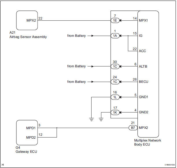
This DTC is detected when communication between the multiplex network body ECU and the multiplex network gateway ECU stops for more than 10 seconds.
|
DTC No. |
DTC Detection Condition |
Trouble Area |
|
B1200 |
Body ECU communication stops |
|
WIRING DIAGRAM
INSPECTION PROCEDURE
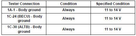
1 CHECK HARNESS AND CONNECTOR (MULTIPLEX NETWORK BODY ECU - BATTERY)
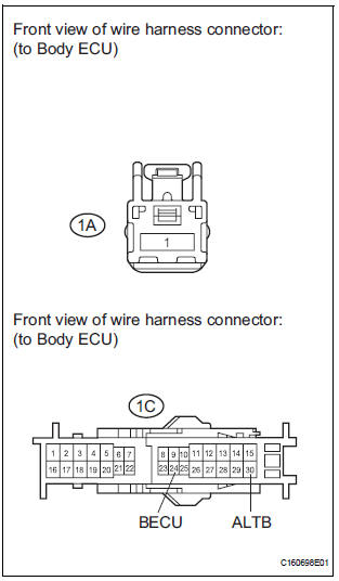
- Disconnect the 1A and 1C junction block connectors.
- Measure the voltage according to the value(s) in the table below.
Standard voltage
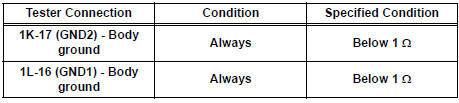
2 CHECK HARNESS AND CONNECTOR (MULTIPLEX NETWORK BODY ECU - GROUND)
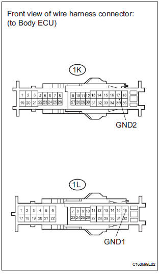
- Disconnect the 1K and 1L junction connectors.
- Measure the resistance according to the value(s) in the table below.
Standard resistance
3 CHECK COMMUNICATION LINE
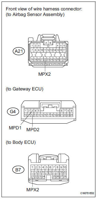
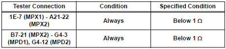
- Disconnect the A21, G4 and B7 ECU connectors.
- Measure the resistance according to the value(s) in the table below.
Standard resistance
Result
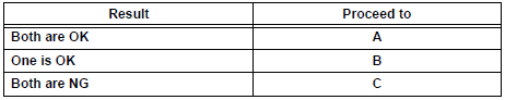
REPLACE MULTIPLEX NETWORK BODY ECU
 Diagnostic trouble code chart
If a malfunction code is displayed during the DTC check,
check the circuit listed for that code in the chart below
(Proceed to the page given for that circuit).
MULTIPLEX COMMUNICATION SYSTEM
...
 Passenger Side Outer Mirror ECU
DTC B1208 Passenger Side Outer Mirror ECU
DESCRIPTION
This DTC is detected when communication between the outer mirror control ECU
RH and multiplex
network gateway ECU stops for more than 10 seco ...
Other materials:
Throttle Actuator Control Motor Current Range
/ Performance
DTC P2118 Throttle Actuator Control Motor Current Range
/ Performance
DESCRIPTION
The ETCS (Electronic Throttle Control System) has a dedicated power supply
circuit. The voltage (+BM)
is monitored and when it is low (less than 4 V), the ECM determines that there
is a malfunction in the
ETCS ...
Removal
HINT:
Remove the RH side by the same procedure as the LH side.
1. REMOVE REAR WHEEL
2. DRAIN BRAKE FLUID
NOTICE:
Wash the brake fluid off immediately if it attaches to
any painted surface.
3. SEPARATE REAR BRAKE TUBE NO.4
(a) Remove the clip and a disconnect, the rear brake
flexible hos ...
Operating instructions
Turning the end of the lever turns on the lights as follows:
The illustration is intended as an example.
U.S.A.
Canada
The headlights, side marker,
parking lights, daytime running
lights (if equipped) and so on turn on and off
automatically (when the engine switch is ...
