Toyota Sienna Service Manual: Terminals of ecu
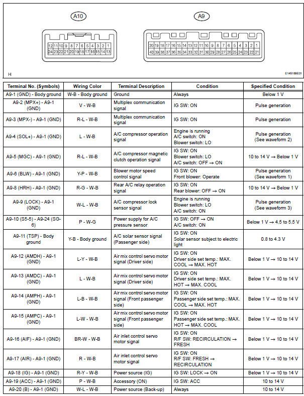
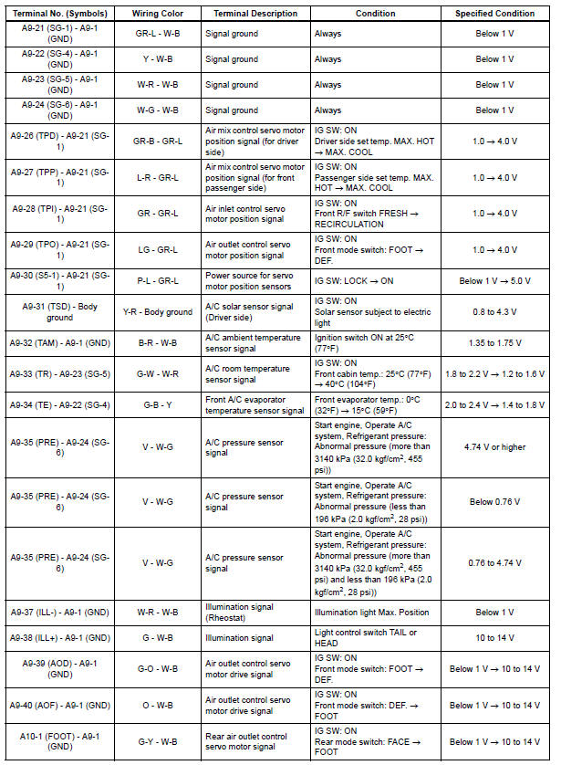
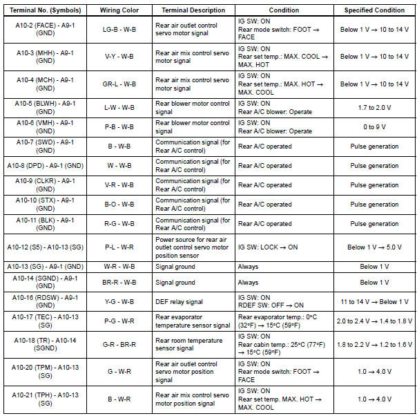
1. A/C AMPLIFIER
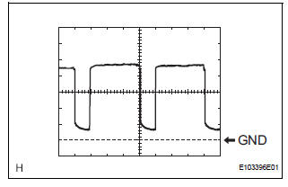
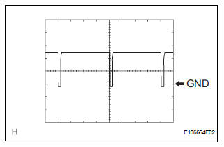
(a) Waveform 1: 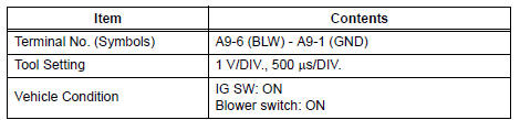
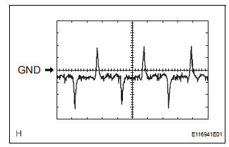
(b) Waveform 2: 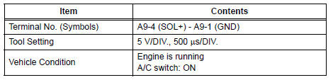
(c) Waveform 3: 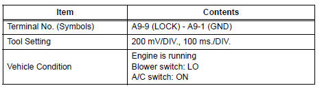
 Parts location
HOW TO PROCEED WITH
TROUBLESHOOTING
1 VEHICLE BROUGHT TO WORKSHOP
2 CUSTOMER PROBLEM ANALYSIS
(a) Confirm problem symptoms.
3 CHECK AND CLEAR DTCS
4 PROBLEM SYMPTOM CONFIRMATIO ...
 Diagnosis system
1. CHECK DLC3
(a) The vehicle's ECM uses the ISO 15765-4 for
communication. The terminal arrangement of the
DLC3 complies with SAE J1962 and matches the
ISO 15765-4 format.
HINT:
Connect the ...
Other materials:
Catalyst System Efficiency Below Threshold
MONITOR DESCRIPTION
The ECM uses the sensors mounted in front of and behind the three-way
catalyst (TWC) to monitor its
efficiency. The first sensor, an Air Fuel ratio (A/F) sensor, sends pre-catalyst
A/F ratio information to the
ECM. The second sensor, a heated oxygen sensor (O2S), sends ...
DTC check / clear
1. CHECK DTC
Prepare the intelligent tester.
Connect the intelligent tester to DLC3.
Turn the ignition switch to the ON position and turn
the intelligent tester main switch ON.
Use the intelligent tester to check the DTCs, and
note them down (For operating instructions, see the
int ...
Accelerator pedal rod
COMPONENTS
ON-VEHICLE INSPECTION
1. CHECK ACCELERATOR PEDAL ROD
(a) Check the voltage.
(1) Connect the intelligent tester to the DLC3.
(2) Turn the ignition switch to the ON position.
(3) Turn the intelligent tester on.
(4) Select the menu items: DIAGNOSIS /
ENHANCED OBD II / D ...
