Toyota Sienna Service Manual: Disassembly
1. REMOVE PROPELLER SHAFT ASSEMBLY
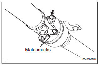
(a) Put matchmarks on both the flanges.
(b) Remove the 4 nuts, bolts and washers.
2. REMOVE INTERMEDIATE SHAFT
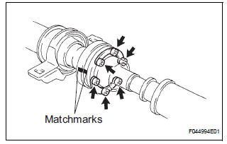
(a) Put matchmarks on the propeller shaft subassembly and universal joint flange.
NOTICE: Do not use a punch for the marks.
(b) Using a hexagon wrench (6 mm), remove the 6 bolts and 2 washers and separate the intermediate shaft from the propeller shaft assembly rear.
3. REMOVE CENTER SUPPORT BEARING ASSEMBLY NO.1
(a) Using a chisel and a hammer, loosen the staked part of the nut.
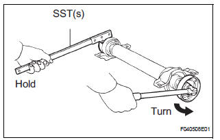
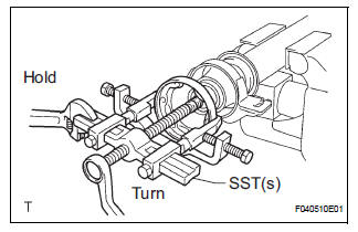
(b) Using SST(s) to hold the front flange, remove the nut and plate washer.
SST 09330-00021
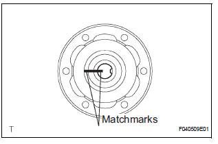
(c) Put matchmarks on the rear flange and shaft.
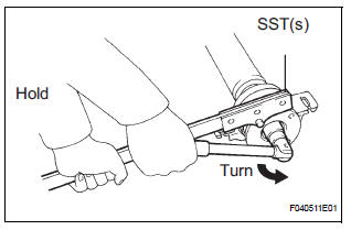
(d) Hold the intermediate shaft in a vise between aluminium plates.
NOTICE: Do not overtighten the vise
(e) Using SST(s), remove the rear flange.
SST 09950-40011 (09951-04020, 09952-04010, 09953-04030, 09954-04010, 09955-04061, 09957-04010, 09958-04011)
NOTICE: Be careful not to damage the universal joint flange.
(f) Remove the center support bearing assembly No. 1 (rear) and washer.
4. REMOVE CENTER SUPPORT BEARING ASSEMBLY NO.1
(a) Using a chisel and a hammer, loosen the staked part of the nut.
(b) Using SST(s) to hold the front flange, remove the nut and plate washer.
SST 09330-00021
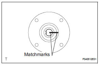
(c) Put matchmarks on the front flange and shaft.
(d) Hold the intermediate shaft in a vise between aluminium plates.
NOTICE: Do not overtighten the vise.
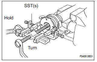
(e) Using SST(s), remove the front flange.
SST 09950-40011 (09951-04020, 09952-04010, 09953-04030, 09954-04010, 09955-04061, 09957-04010, 09958-04011)
NOTICE: Be careful not to damage the universal joint flange.
(f) Remove the center support bearing assembly No. 1 (front) and washer.
 Removal
1. REMOVE EXHAUST PIPE ASSEMBLY
(a) Remove exhaust pipe assembly (See page EX-8).
2. REMOVE PROPELLER W/CENTER BEARING SHAFT ASSEMBLY
(a) Depress the brake pedal and hold it down.
(b) Using ...
 Inspection
1. INSPECT SPIDER BEARING
(a) Check that the spider bearing moves smoothly by
turning the flange.
(b) Check for the looseness around the joint by strongly
moving the flange in the axial and ...
Other materials:
Removal
1. REMOVE FRONT FENDER LINER LH
2. REMOVE FRONT FENDER LINER RH
3. REMOVE FRONT BUMPER COVER
4. REMOVE FRONT BUMPER ENERGY ABSORBER
5. REMOVE FRONT BUMPER REINFORCEMENT SUBASSEMBLY
6. REMOVE LASER SENSOR
Disconnect the connector and remove the laser the
sensor.
...
If the vehicle becomes
stuck
Carry out the following procedures if the tires spin or the vehicle
becomes stuck in mud, dirt, or snow:
Stop the engine. Set the parking brake and shift the shift lever to P.
Remove the mud, snow, or sand from around the stuck tire.
Place wood, stones or some other material under the tires ...
Data list / active test
1. READ DATA LIST
HINT:
Using the intelligent tester's DATA LIST allows switch,
actuator and other item values to be read without
removing any parts. Reading the DATA LIST early in
troubleshooting is one way to save time.
Connect the intelligent tester with CAN VIM to the
DLC3.
&n ...
