Toyota Sienna Service Manual: Removal
1. REMOVE EXHAUST PIPE ASSEMBLY
(a) Remove exhaust pipe assembly (See page EX-8).
2. REMOVE PROPELLER W/CENTER BEARING SHAFT ASSEMBLY
(a) Depress the brake pedal and hold it down.
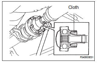
(b) Using a hexagon wrench (6 mm), loosen the cross groove joint set bolts a half turn.
HINT: Place a cloth in the inside of the universal joint cover so that the boot does not touch the inside of the universal joint cover.
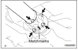
(c) Put matchmarks on both the flanges.
(d) Remove the 4 nuts, bolts and washers.
(e) Remove the 4 bolts, 2 adjusting shims and propeller shaft w/ center bearing shaft assembly.
NOTICE:
- When removing the propeller shaft, do not apply excessive force to the universal joint.
- During and after the removal of the propeller shaft, keep the universal joint angle straight (within 15 degrees).
- Be careful not to damage the oil seal.
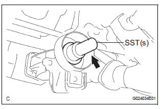
(f) Insert SST(s) in the transfer extension housing to prevent oil leakage.
SST 09325-20010
NOTICE: Be careful not to damage the oil seal.
 Propeller shaft assembly (for 4wd)
COMPONENTS
...
 Disassembly
1. REMOVE PROPELLER SHAFT ASSEMBLY
(a) Put matchmarks on both the flanges.
(b) Remove the 4 nuts, bolts and washers.
2. REMOVE INTERMEDIATE SHAFT
(a) Put matchmarks on the propeller shaf ...
Other materials:
No. 1 Ultrasonic sensor
COMPONENTS
REMOVAL
1. REMOVE FRONT FENDER LINER LH
2. REMOVE FRONT FENDER LINER RH
3. REMOVE FRONT BUMPER COVER
4. REMOVE REAR BUMPER COVER (2)
5. REMOVE NO. 1 ULTRASONIC SENSOR RETAINER
Remove the No. 1 ultrasonic sensor retainer as
shown in the illustration
6. REMOVE ...
Adjustment
HINT:
On the RH side, use the same procedures as on the LH side.
1. INSPECT SLIDE DOOR PANEL SUB-ASSEMBLY LH
Check that the clearance is within the standard
range.
Standard
2. ADJUST SLIDE DOOR PANEL SUB-ASSEMBLY LH
Using the SST, horizontally and vertically adjust the
do ...
Operation flow
HINT:
Perform troubleshooting in accordance with the
procedures below. The following is an outline of basic
troubleshooting procedures. Confirm the troubleshooting
procedures for the circuit you are working on before
beginning troubleshooting.
VEHICLE BROUGHT TO WORKSHOP
CUSTOMER PR ...
