Toyota Sienna Service Manual: Disassembly
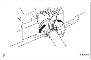
1. REMOVE NO. 2 FRONT AXLE INBOARD JOINT BOOT LH CLAMP
(a) Using pliers, remove the No. 2 front axle inboard joint boot LH clamp, as shown in the illustration.
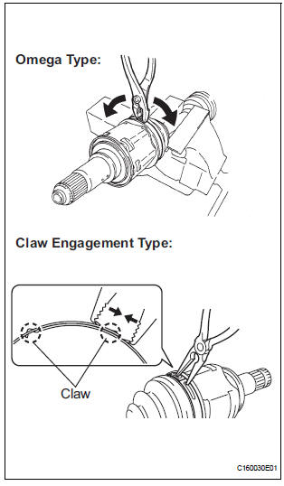
2. REMOVE FRONT AXLE INBOARD JOINT BOOT LH CLAMP
(a) Remove the front axle inboard joint boot LH clamp using the same procedures as for the No. 2 front axle inboard joint boot LH clamp.
3. SEPARATE FR AXLE INBOARD JOINT BOOT
(a) Separate the inboard joint boot from the inboard joint assembly.
4. REMOVE FRONT DRIVE INBOARD JOINT ASSEMBLY LH
(a) Remove the grease from the inboard joint.
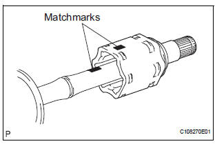
(b) Put matchmarks on the inboard joint shaft assembly and outboard joint shaft.
NOTICE: Do not use a punch for the marks.
(c) Remove the inboard joint shaft assembly from the outboard joint shaft.
(d) Using a snap ring expander, remove the snap ring.
(e) Put matchmarks on the outboard joint shaft and tripod.
NOTICE: Do not use a punch for the marks.
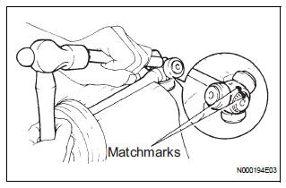
(f) Using a brass bar and hammer, remove the tripod from the outboard joint shaft.
NOTICE: Do not tap the roller.
5. REMOVE FR AXLE INBOARD JOINT BOOT
(a) Remove the inboard joint boot and inboard joint boot clamp.
6. REMOVE FRONT DRIVE SHAFT DAMPER CLAMP
(a) Using pliers, remove the front drive shaft damper clamp, as shown in the illustration.
7. REMOVE FRONT DRIVE SHAFT DAMPER
(a) Remove the drive shaft damper.
8. REMOVE OUTBOARD JOINT BOOT NO. 2 CLAMP
(a) Using pliers, remove the outboard joint boot No. 2 clamp, as shown in the illustration.
9. REMOVE OUTBOARD JOINT BOOT CLAMP
(a) Remove the outboard joint boot clamp perform the same procedures as for the outboard joint boot No.
2 clamp.
10. REMOVE OUTBOARD JOINT BOOT
(a) Remove the outboard joint boot from the outboard joint shaft.
(b) Remove the grease from the outboard joint.
11. REMOVE FRONT DRIVE SHAFT LH HOLE SNAP RING
(a) Using a screwdriver, remove the front drive shaft LH hole snap ring.
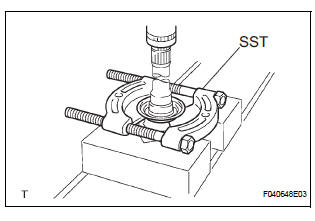
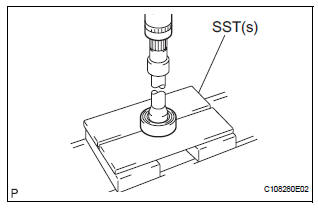
12. REMOVE FRONT DRIVE SHAFT DUST COVER LH
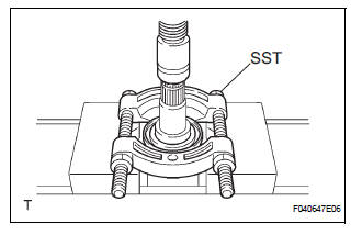
(a) Using SST and a press, remove the drive shaft dust cover LH.
SST 09950-00020
NOTICE: Be careful not to drop the inboard joint assembly.
13. REMOVE FRONT DRIVE SHAFT DUST COVER RH (for 2WD)
(a) Using a press, remove the drive shaft dust cover RH.
14. REMOVE FRONT DRIVE SHAFT DUST COVER RH (for 4WD)
(a) Using SST and a press, remove the drive shaft dust cover RH.
SST 09950-00020
NOTICE: Be careful not to drop the inboard joint assembly.
15. REMOVE FRONT DRIVE SHAFT DUST COVER
(a) Using SST and a press, remove the drive shaft dust cover.
SST 09950-00020
NOTICE: Be careful not to drop the inboard joint assembly.
16. REMOVE FRONT DRIVE SHAFT RH HOLE SNAP RING
(a) Using a snap ring expander, remove the drive shaft RH hole snap ring.
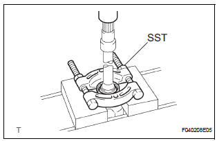
17. REMOVE FRONT DRIVE SHAFT BEARING
(a) Using SST and a press, remove the front drive shaft bearing.
SST 09527-10011
 Removal
1. Drain automatic transaxle fluid
(a) Remove the drain plug, gasket and drain ATF.
(b) Install a new gasket and the drain plug.
Torque: 49 N*m (500 kgf*cm, 36 ft.*lbf)
2. Drain transfer oil ( ...
 Inspection
1. INSPECT FRONT DRIVE SHAFT ASSEMBLY LH
(a) Check that there is no remarkable play in the radial
direction of the outboard joint.
(b) Check that the inboard joint slides smoothly in the
thr ...
Other materials:
Terminals of ECU
1. CHECK POWER BACK DOOR ECU
Disconnect the P13 and P14 ECU connectors, and
check the voltage or resistance of each terminal of
the wire harness side connectors
If the result is not as specified, there may be a
malfunction on the wire harness side.
Reconnect the ECU connector ...
Engine unit
COMPONENTS
...
Brake control
Sst
Recommended tools
HINT:
Torx is a registered trademark of Textron Inc.
EQUIPMENT
LUBRICANT
BRAKE
SST
RECOMMENDED TOOLS
EQUIPMENT
LUBRICANT
PARKING BRAKE
EQUIPMENT
STEERING COLUMN
SST
EQUIPMENT
...
