Toyota Sienna Service Manual: Auto Up / Down Function does not Operate
DESCRIPTION
If the AUTO UP/DOWN function does not operate, any of the following troubles may be the cause:
- When the PWR fuse or the power window relay (Marking: PWR) is replaced with new ones, or when the battery terminal and the connector of the power window master switch are disconnected, the power window memory of the fully closed position which is recorded in the power window master switch is erased.
- The pulse sensors in the driver side power window motor have a malfunction.
- There is an open or short circuit in the wiring between the power window master switch and the driver side power window motor.
- The power window master switch has a malfunction.
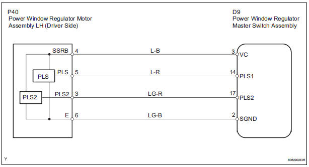
WIRING DIAGRAM
INSPECTION PROCEDURE
1 CHECK MANUAL UP/DOWN FUNCTION (DRIVER SIDE)
- Check that the door glass can be operated manually.
2 CHECK ILLUMINATION OF POWER WINDOW MASTER SWITCH
- Turn the ignition switch ON.
- Operate the AUTO (drive side) switch of the master switch.
- Check the blinking pattern of the AUTO light as shown in the illustration.
- If pattern (1) is displayed, proceed to A.
- If pattern (2) or (3) is displayed, proceed to B.
- If the normal pattern is displayed, proceed to C.

3 RESET POWER WINDOW REGULATOR MOTOR
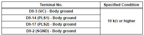
4 CHECK WIRE HARNESS (MASTER SWITCH - MOTOR) (MASTER SWITCH - BODY GROUND)
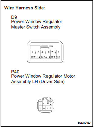
- Disconnect the D9 master switch connector.
- Disconnect the P40 motor connector (driver side).
- Check the resistance between the wire harness side connectors.
Standard resistance
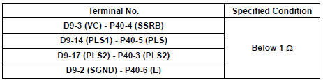
- Check the resistance between the D9 master switch connector and body ground.
Standard resistance
REPLACE POWER WINDOW REGULATOR MOTOR ASSEMBLY (DRIVER SIDE)
 Data list / active test
1. USING INTELLIGENT TESTER
Connect the intelligent tester to the DLC3.
Monitor the ECU data by following the prompts on
the tester screen.
HINT:
The intelligent tester has a & ...
 Remote Up / Down Function does not Operate
DESCRIPTION
If the REMOTE UP/DOWN function does not operate, any of the following
troubles may be the cause:
There is an open or short circuit in the wiring between the power
window ma ...
Other materials:
Removal
1. REMOVE FRONT WHEEL
2. REMOVE REAR WHEEL
3. REMOVE TIRE PRESSURE WARNING VALVE AND TRANSMITTER
(a) Remove the valve core and cap, and release the air
from the tire.
(b) After ensuring that a sufficient amount of air has
been released, remove the nut and washer that are
used to secure ...
Data list / active test
1. READ DATA LIST
HINT:
Using the intelligent tester's DATA LIST allows switch,
actuator and other item values to be read without
removing any parts. Reading the DATA LIST early in
troubleshooting is one way to save time.
Connect the intelligent tester with CAN VIM to the
DLC3.
&n ...
Short to GND in Curtain Shield Squib RH Circuit
DTC B1162/81 Short to GND in Curtain Shield Squib RH Circuit
DESCRIPTION
The curtain shield squib RH circuit consists of the center airbag sensor
assembly and the curtain shield
airbag assembly RH.
The circuit instructs the SRS to deploy when deployment conditions are met.
DTC B1162/81 is ...
