Toyota Sienna Service Manual: Stereo Component Amplifier Power Source Circuit
DESCRIPTION
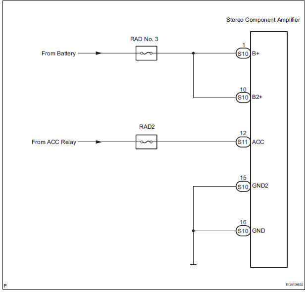
This circuit provides power to the stereo component amplifier.
WIRING DIAGRAM
INSPECTION PROCEDURE
1 INSPECT STEREO COMPONENT AMPLIFIER
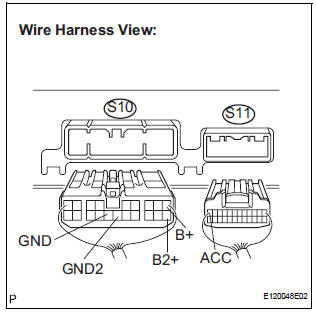
- Disconnect the stereo component amplifier connector.
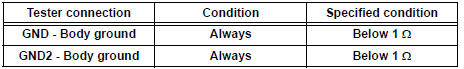
- Measure the resistance according to the value(s) in the table below.
Standard resistance
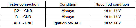
- Measure the voltage according to the value(s) in the table below.
Standard voltage
PROCEED TO NEXT CIRCUIT INSPECTION SHOWN IN PROBLEM SYMPTOMS TABLE
 Television Display Assembly Communication Error
INSPECTION PROCEDURE
1 IDENTIFY THE COMPONENT SHOWN BY THE SUB-CODE
Enter the diagnostic mode.
Press the "LAN Mon" switch to change to "LAN Monitor"
mode.
&nbs ...
 Radio and Navigation Assembly Power Source Circuit
DESCRIPTION
This is the power source circuit to operate the radio and navigation
assembly.
WIRING DIAGRAM
INSPECTION PROCEDURE
1 INSPECT RADIO AND NAVIGATION ASSEMBLY
Disconnect the ...
Other materials:
Inspection
1. INSPECT FRONT SPEED SENSOR
(a) Make sure that there is no looseness at the
connector lock part and connecting part of the
connector.
(b) Disconnect the speed sensor connector.
(c) Measure the resistance between terminals 1 and 2
of the speed sensor connector.
OK:
Resistance:
0.92 ...
On-vehicle inspection
1. INSPECT BACK WINDOW (DEFOGGER WIRE)
NOTICE:
When cleaning the glass, wipe the glass along the
wire using a soft and dry cloth. Take care not to
damage the wires.
Do not use detergents or glass cleaners including
abrasive ingredients.
When measuring voltage, wr ...
Installing the spare tire
Remove any dirt or foreign matter
from the wheel contact surface.
If foreign matter is on the wheel
contact surface, the wheel nuts
may loosen while the vehicle is in
motion, causing the tire to come
off.
Install the tire and loosely
tighten each wheel nut by hand
by ...
