Toyota Sienna Service Manual: Disposal
HINT: On the RH side, use the same procedures as on the LH side.
1. DISPOSE OF BACK DOOR STAY SUB-ASSEMBLY LH
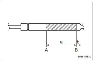
- Horizontally fix the stay in a vise with the piston-rod pulled out.
- Wearing safety glasses, gradually cut a part between A and B as shown in the illustration using a metal saw to gradually release the gas.
Dimensions
NOTICE: Although the gas inside the damper stay is colorless, odorless and harmless, there is a possibility that metal debris from cutting could enter the assembly. Therefore, cover it with cloth or something similar.
 Installation
1. REMOVE BACK DOOR STAY SUB-ASSEMBLY LH
Install the stay with the bolts to the door panel.
Torque: 19.5 N*m (200 kgf*cm, 14 ft.*lbf) for
door side
Install the stay with the 2 bolts to the b ...
 Power slide door control motor and clutch
INSPECTION
1. INSPECT SLIDE DOOR CONTROL MOTOR AND CLUTCH ASSEMBLY LH
Remove the motor and clutch.
Connect the battery positive (+) lead to terminal 3
and the battery negative (-) lead to ...
Other materials:
How to proceed with
troubleshooting
HINT:
Use the following procedures to troubleshoot the dynamic
laser cruise control system.
*: Use the intelligent tester
1 VEHICLE BROUGHT TO WORKSHOP
2 CUSTOMER PROBLEM ANALYSIS
3 PROBLEM SYMPTOM CONFIRMATION
Result
SYMPTOM SIMULATION
4 INSPECT BATTERY VOLTAGE
Stan ...
Removal
1. REMOVE INSTRUMENT CLUSTER CENTER NO. 1 FINISH PANEL
2. REMOVE INSTRUMENT CLUSTER CENTER NO. 2
FINISH PANEL
3. REMOVE SHIFT LEVER KNOB SUB-ASSEMBLY
4. REMOVE POSITION INDICATOR HOUSING ASSEMBLY
5. REMOVE INSTRUMENT CLUSTER CENTER LOWER FINISH PANEL SUB-ASSEMBLY
6. REMOVE POWER POINT SOCKET A ...
Parking brake
Operating instructions
To set the parking brake, fully
depress the parking brake pedal
with your left foot while depressing
the brake pedal with your right
foot.
(Depressing the pedal again
releases the parking brake.)
Usage in winter time
NOTICEBefore driving
Fully release ...
