
Toyota Sienna Service Manual: Power slide door control motor and clutch
INSPECTION
1. INSPECT SLIDE DOOR CONTROL MOTOR AND CLUTCH ASSEMBLY LH
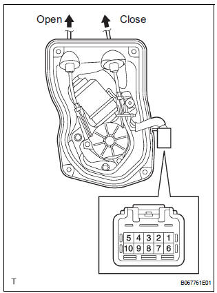
- Remove the motor and clutch.
- Connect the battery positive (+) lead to terminal 3 and the battery negative (-) lead to terminal 2.
- Apply battery voltage to the terminals and check the motor operation.
OK
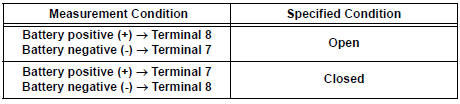
If the result is not as specified, replace the motor and clutch.
- Check the resistance of the terminals.
Resistance

If the result is not as specified, replace the motor and clutch.
- Reinstall the motor and clutch with the connector connected.
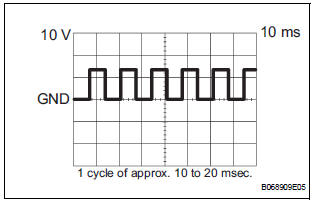
- Check the pulse of the pulse sensor.
- Using an oscilloscope, check the pulse generated when the door is manually opened and closed.
Reference

If the result is not as specified, replace the motor and clutch.
HINT: The cycle of the pulse changes between approx. 10 to 20 msec. according to the speeds that the slide door is moving.
2. REMOVE SLIDE DOOR CONTROL MOTOR AND CLUTCH ASSEMBLY RH
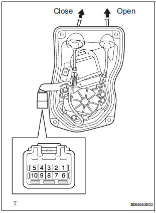
- Remove the motor and clutch.
- Connect the battery positive (+) lead to terminal 3 and the battery negative (-) lead to terminal 2.
- Apply battery voltage to the terminals and check the motor operation.
OK
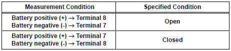
If the result is not as specified, replace the motor and clutch.
- Check the resistance of the terminals.
Resistance

If the result is not as specified, replace the motor and clutch.
- Reinstall the motor and clutch with the connector connected.
- Check the pulse of the pulse sensor.
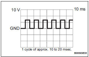
- Using an oscilloscope, check the pulse generated when the door is manually opened and closed.
Reference

If the result is not as specified, replace the motor and clutch.
HINT: The cycle of the pulse changes between approx. 10 to 20 msec. according to the speeds that the slide door is moving.
 Disposal
HINT:
On the RH side, use the same procedures as on the LH side.
1. DISPOSE OF BACK DOOR STAY SUB-ASSEMBLY LH
Horizontally fix the stay in a vise with the piston-rod
pulled out.
Wearing ...
 Power slide door
COMPONENTS
...
Other materials:
Input instructions
(a) The general VIN input instructions using the
intelligent tester are shown below:
(b) The arrow buttons (UP, DOWN, RIGHT and LEFT)
and numerical buttons (0 to 9) are used to input the
VIN.
(c) Cursor Operation
To move the cursor around the tester screen, press
the RIGHT and LEFT buttons. ...
Operating Light Control Rheostat does not Change Light Brightness
DESCRIPTION
The meter CPU receives signals for adjusting illumination on the meter from
this circuit. The meter CPU
detects the illumination level selected by the user according to the position of
the rheostat knob.
WIRING DIAGRAM
INSPECTION PROCEDURE
1 READ VALUE OF INTELLIGENT TESTER ...
Inspection
1. INSPECT SHOCK ABSORBER ASSEMBLY FRONT LH
(a) Compress and extend the shock absorber rod and
check that there is no unusual resistance or unusual
sound during operation.
If there is any abnormality, replace the shock
absorber assembly front LH with a new one.
NOTICE:
When disposing of ...
