Toyota Sienna Service Manual: Distance Control ECU Communication Stop Mode
DESCRIPTION
|
Detection Item |
Symptom |
Trouble Area |
| Distance Control ECU Communication Stop Mode |
|
|
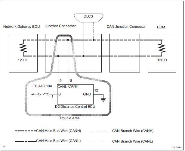
WIRING DIAGRAM
INSPECTION PROCEDURE
NOTICE:
- Turn the ignition switch off before measuring the resistances of CAN bus main wires and CAN bus branch wires.
- After the ignition switch is turned off, check that the key reminder warning system and light reminder warning system are not in operation.
- Before measuring the resistance, leave the vehicle as is for at least 1 minute and do not operate the ignition switch, any other switches, or the doors. If any doors need to be opened in order to check connectors, open the doors and leave them open.
HINT: Operating the ignition switch, any switches, or any doors triggers related ECU and sensor communication with the CAN. This communication will cause the resistance value to change.
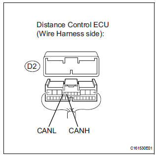
1 CHECK OPEN IN CAN BUS WIRE (DISTANCE CONTROL ECU)
- Turn the ignition switch off.
- Disconnect the distance control ECU connector.
- Measure the resistance according to the value(s) in the table below.
Standard resistance

2 CHECK WIRE HARNESS (B, GND)
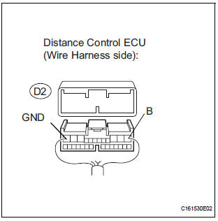
- Measure the resistance according to the value(s) in the table below.
Standard resistance

- Measure the voltage according to the value(s) in the table below.
Standard voltage
REPLACE DISTANCE CONTROL ECU ASSEMBLY
 Skid Control ECU Communication Stop Mode
DESCRIPTION
Detection Item
Symptom
Trouble Area
Skid Control ECU
Communication Stop
Mode
"ABS/VSC/TRC" is not displayed on the
" ...
 Gateway ECU Communication Stop Mode
DESCRIPTION
Detection Item
Symptom
Trouble Area
Gateway ECU
Communication Stop
Mode
"Gateway" is not displayed on the "Communication ...
Other materials:
Removal
HINT:
Use the same procedures for the RH side and LH side.
The procedures listed below are for the LH side.
1. PRECAUTION
CAUTION:
Be sure to read "PRECAUTION" thoroughly before
servicing.
2. DISCONNECT CABLE FROM NEGATIVE BATTERY
TERMINAL
CAUTION:
Wait for 90 s ...
Short to B+ in Side Squib RH Circuit
DTC B0113/42 Short to B+ in Side Squib RH Circuit
DESCRIPTION
The side squib RH circuit consists of the center airbag sensor assembly and
the front seat side airbag
assembly RH.
This circuit instructs the SRS to deploy when deployment conditions are met.
DTC B0113/42 is recorded when a sh ...
No. 2 Ultrasonic sensor
COMPONENTS
REMOVAL
1. REMOVE REAR BUMPER COVER (2)
2. REMOVE NO. 1 ULTRASONIC SENSOR RETAINER
Remove the No. 1 ultrasonic sensor retainer as
shown in the illustration
3. REMOVE NO. 2 ULTRASONIC SENSOR
Disconnect the connector and remove the No. 2
ultrasonic ...
