Toyota Sienna Service Manual: Reverse Signal Circuit
DESCRIPTION
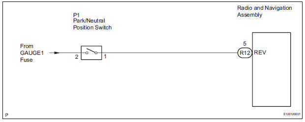
The radio and navigation assembly receives a reverse signal from the park/neutral position switch.
WIRING DIAGRAM
INSPECTION PROCEDURE
1 INSPECT RADIO AND NAVIGATION ASSEMBLY
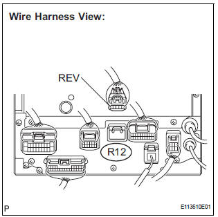
- Disconnect the radio and navigation assembly connector R12.
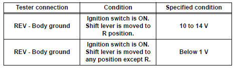
- Measure the voltage according to the value(s) in the table below.
Standard voltage
2 CHECK HARNESS AND CONNECTOR (RADIO AND NAVIGATION ASSEMBLY - PARK/ NEUTRAL POSITION SWITCH)
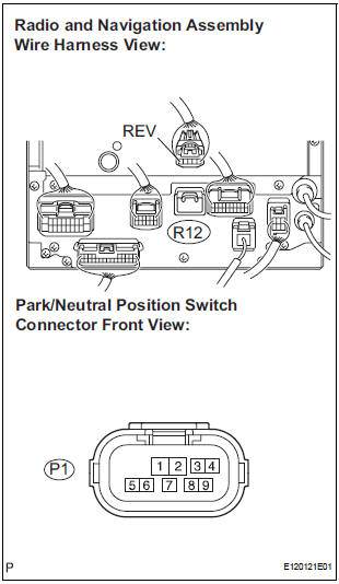
- Disconnect the radio and navigation assembly connector R12 and park/neutral position switch connector P1.
- Measure the resistance according to the value(s) in the table below.
Standard resistance
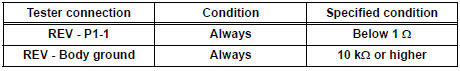
3 INSPECT PARK/NEUTRAL POSITION SWITCH ASSEMBLY
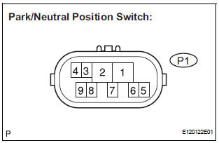
- Disconnect the park/neutral position switch connector P1.
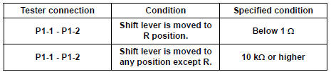
- Measure the resistance according to the value(s) in the table below.
Standard resistance
REPAIR OR REPLACE HARNESS OR CONNECTOR
 Terminals of ECU
1. TELEVISION CAMERA ASSEMBLY
Disconnect the T10 camera connector
Measure the voltage and resistance of each
terminal of the wire harness side connector.
If the result is ...
 Display Signal Circuit between Radio and Navigation Assembly and
Television Camera Assembly
Display Signal Circuit between Radio and Navigation Assembly and
Television Camera Assembly
DESCRIPTION
This is the display signal circuit of the television camera assembly.
WIRING DIAGRAM
INSPECTION PROCEDURE
1 CHECK HARNESS AND CONNECTOR (RADIO AND NAVIGATION ASSEMBLY - TELEVISION ...
Other materials:
Engine front oil seal
COMPONENTS
REMOVAL
1. REMOVE FRONT WHEEL RH
2. REMOVE FRONT FENDER APRON SEAL RH (See
page EM-26)
3. REMOVE V-RIBBED BELT (See page EM-6)
4. REMOVE CRANKSHAFT PULLEY
(a) Using SST, loosen the crankshaft pulley bolt.
SST 09213-70011 (09213-70020), 09330-00021
(b) Using SST, remove ...
Diagnosis system
1. CHECK DLC3
The vehicle uses ISO 15765-4 communication
protocol.
The terminal arrangement of the DLC3 complies
with SAE 1962 and matched the ISO 15765-4
format.
If the result is not as specified, the DLC3 may have
a malfunction. Repair or replace the harness and
connecto ...
Brake Switch
DTC P0504 Brake Switch "A" / "B" Correlation
DTC P0724 Brake Switch "B" Circuit High
DESCRIPTION
The stop light switch is a duplex system that transmits two signals: STP and
ST1-. These two signals are
used by the ECM to monitor whether or not the brake system is ...
