Toyota Sienna Service Manual: Gateway ECU Communication Stop Mode
DESCRIPTION
|
Detection Item |
Symptom |
Trouble Area |
| Gateway ECU Communication Stop Mode |
|
|
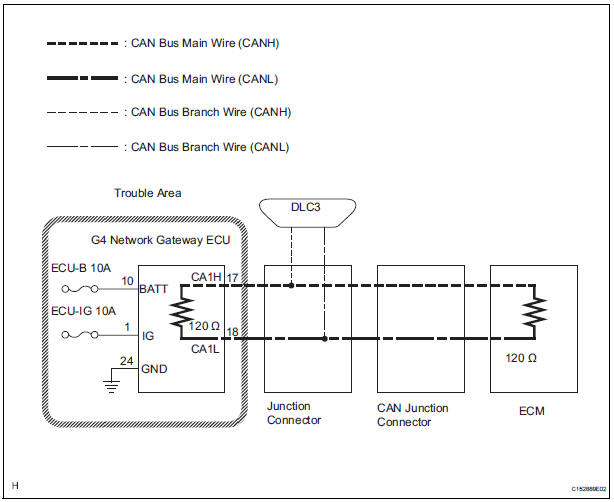
WIRING DIAGRAM
INSPECTION PROCEDURE
NOTICE:
- Turn the ignition switch off before measuring the resistances of CAN bus main wires and CAN bus branch wires.
- After the ignition switch is turned off, check that the key reminder warning system and light reminder warning system are not in operation.
- Before measuring the resistance, leave the vehicle as is for at least 1 minute and do not operate the ignition switch, any other switches, or the doors. If any doors need to be opened in order to check connectors, open the doors and leave them open.
HINT: Operating the ignition switch, any switches, or any doors triggers related ECU and sensor communication with the CAN. This communication will cause the resistance value to change.
1 CHECK OPEN IN CAN BUS WIRE (ECU MAIN BUS WIRE)
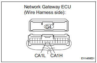
- Turn the ignition switch off.
- Disconnect the network gateway ECU connector.
- Measure the resistance according to the value(s) in the table below.
Standard resistance

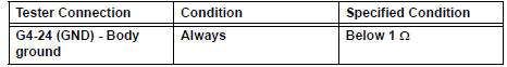
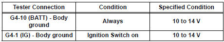
2 CHECK WIRE HARNESS (IG, BATT, GND)
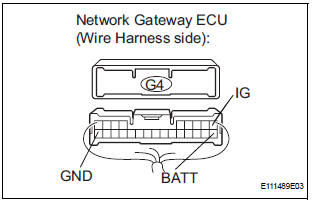
- Measure the resistance according to the value(s) in the table below.
Standard resistance
- Measure the voltage according to the value(s) in the table below.
Standard voltage
REPLACE NETWORK GATEWAY ECU
 Distance Control ECU Communication Stop Mode
DESCRIPTION
Detection Item
Symptom
Trouble Area
Distance Control ECU
Communication Stop
Mode
Distance control" is not displayed on the
&qu ...
 Steering Angle Sensor Communication Stop Mode
DESCRIPTION
Detection Item
Symptom
Trouble Area
Steering Angle Sensor
Communication Stop
Mode
"Steering angle sensor" is not displayed on ...
Other materials:
Installation
1. INSTALL THROTTLE BODY
Install a new throttle body gasket to the intake air
surge tank.
Install the throttle body with the 4 bolts.
Torque: 10 N*m (102 kgf*cm, 7 ft.*lbf)
Connect the 2 water by-pass hoses.
Connect the throttle body connector and clamp.
2. ...
Transfer
SST
RECOMMENDED TOOLS
EQUIPMENT
LUBRICANT
SSM
...
Data list / active test
HINT:
By accessing the DATA LIST displayed on the intelligent
tester, you can perform such functions as reading the values
of switches and sensors without removing any parts. Reading
the DATA LIST as the first step in troubleshooting is one
method to shorten labor time.
1. DATA LIST FOR CENTER ...
