Toyota Sienna Service Manual: Distance Control ECU Power Source Circuit
DESCRIPTION
This circuit provides power to operate the distance control ECU. The distance control ECU determines information about the vehicle in front based on data from the laser sensor, and then decides how much acceleration and/or deceleration is needed to maintain the set distance. The distance control ECU also requests the skid control ECU to apply braking and to sound the buzzer.
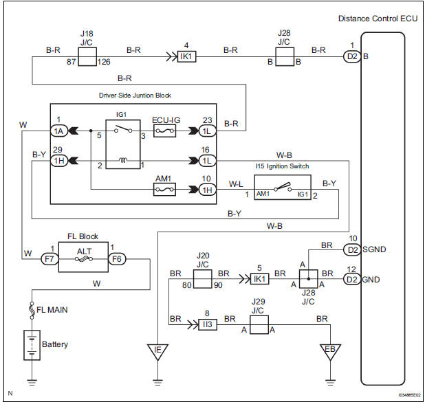
WIRING DIAGRAM
INSPECTION PROCEDURE
1 CHECK HARNESS AND CONNECTOR
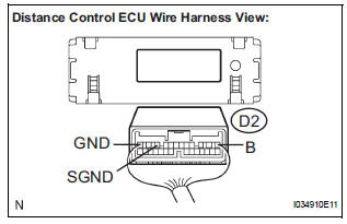
- Disconnect the D2 distance control ECU connector.
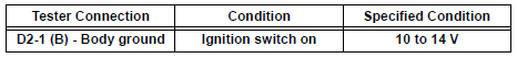
- Measure the voltage according to the value(s) in the table below.
Standard voltage
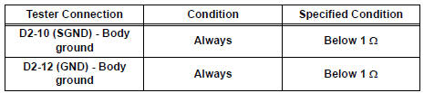
- Measure the resistance according to the value(s) in the table below.
Standard resistance
PROCEED TO NEXT CIRCUIT INSPECTION SHOWN IN PROBLEM SYMPTOMS TABLE
 Cruise Control Switch Circuit
DESCRIPTION
The cruise control main switch operates 8 functions: SET, - (COAST),
TAP-DOWN, RES (RESUME), +
(ACCEL), TAP-UP, CANCEL, and MODE. The SET, TAP-DOWN, and - (COAST) functions,
and the ...
 Distance Control Switch Circuit
DESCRIPTION
The distance control switch sets the vehicle-to-vehicle distance mode. The
distance control switch is
installed in the steering pad switch. The vehicle-to-vehicle distance set value
...
Other materials:
Precaution
1. INITIALIZATION
NOTICE:
Perform RESET MEMORY (AT initialization) when
replacing the automatic transaxle assembly, engine
assembly or ECM.
Perform REGISTRATION (VIN registration) when
replacing the ECM.
HINT:
Initialization cannot be completed by only removing the
batt ...
Diagnosis system
1. CHECK DLC3
The ECU uses ISO 15765-4 for communication.
The terminal arrangement of the DLC3 complies
with SAE J1962 and matches the ISO 15765-4
format.
NOTICE:
*: Before measuring the resistance, leave the
vehicle as is for at least 1 minute and do not
operate the igniti ...
Fail-safe chart
1. FAIL-SAFE
This function minimizes the loss of the ECT functions
when any malfunction occurs in a sensor or solenoid.
(a) ATF (Automatic Transmission Fluid) temperature
sensor:
When the ATF temperature sensor has a
malfunction, 5th upshift is prohibited.
(b) Counter gear speed sensor NC ...
