
Toyota Sienna Service Manual: Distance Control Switch Circuit
DESCRIPTION
The distance control switch sets the vehicle-to-vehicle distance mode. The distance control switch is installed in the steering pad switch. The vehicle-to-vehicle distance set value can be changed by operating the steering pad switch (distance control switch) while the dynamic laser cruise control system is in operation.
WIRING DIAGRAM
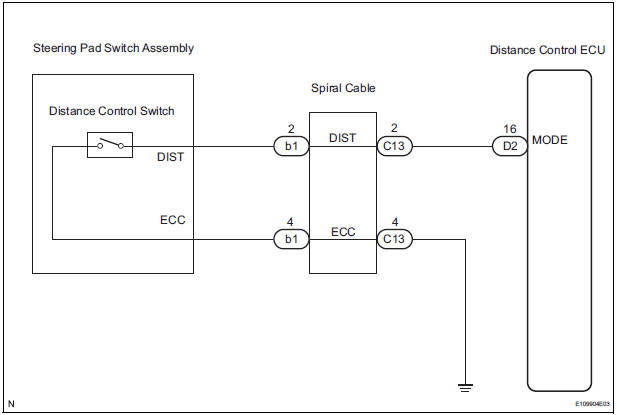
INSPECTION PROCEDURE
1 INSPECT STEERING PAD SWITCH ASSEMBLY
- Remove the steering pad switch assembly
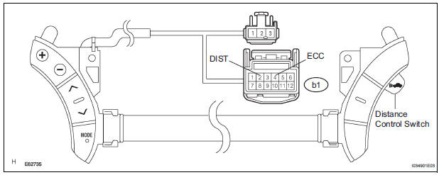
- Measure the resistance according to the value(s) in the table below.
Standard resistance
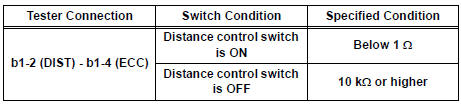
HINT: When a malfunction is detected in the distance control switch, replace the steering pad switch assembly.
2 INSPECT SPIRAL CABLE
NOTICE: The spiral cable is an important part of the SRS airbag system. Incorrect removal or installation of the spiral cable may cause airbag deployment. Be sure to read the page shown in the brackets.
HINT:
- Removal (34)
- Installation
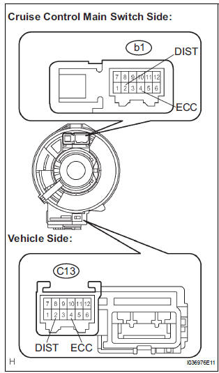
- Remove the spiral cable.
- Measure the resistance according to the value(s) in the table below.
Standard resistance
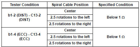
HINT: The spiral cable makes a maximum of approximately 5 rotations.
3 CHECK HARNESS AND CONNECTOR (DISTANCE CONTROL ECU - SPIRAL CABLE)
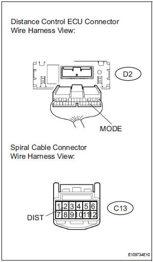
- Disconnect the D2 distance control ECU connector.
- Measure the resistance according to the value(s) in the table below.
Standard resistance
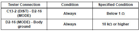
4 CHECK HARNESS AND CONNECTOR (SPIRAL CABLE - BODY GROUND)
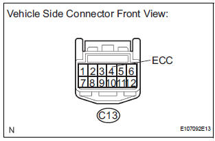
- Measure the resistance according to the value(s) in the table below.
Standard resistance

5 INSPECT DISTANCE CONTROL ECU
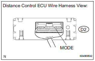
- Remove the distance control ECU with the connector.
- Turn the ignition switch to the ON position.
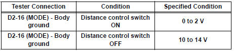
- Measure the voltage according to the value(s) in the table below.
Standard voltage
PROCEED TO NEXT CIRCUIT INSPECTION SHOWN IN PROBLEM SYMPTOMS TABLE
 Distance Control ECU Power Source Circuit
DESCRIPTION
This circuit provides power to operate the distance control ECU. The distance
control ECU determines
information about the vehicle in front based on data from the laser sensor, and
t ...
 Laser Sensor Power Source Circuit
DESCRIPTION
This circuit provides power to the laser sensor. The laser sensor emits radio
waves towards an object in
front and measures the distance and direction of the object by receiving the
...
Other materials:
Master cylinder pressure sensor check (when using intelligent tester)
(a) Leave the vehicle in a stationary condition and
release the brake pedal for 1 second or more, and
quickly depress the brake pedal with a force of 98 N
(10 kgf, 22 lbf) or more for 1 second or more.
(b) Check the ABS warning light stays on for 3
seconds
HINT:
Ensure that the ABS warni ...
GPS Mark is not Displayed
INSPECTION PROCEDURE
1 CHECK CABIN
Check the cabin for any object that might interrupt radio
reception on the instrument panel. If such an object
exists, remove it and check if the GPS mark reappears.
HINT:
The GPS uses extremely faint radio waves originating
from satellites. If the si ...
Problem symptoms table
Proceed to the reference page shown in the table below for
each malfunction symptom and troubleshoot each circuit.
HINT:
Troubleshooting of the theft deterrent system is based on the
premise that the door lock control system and the wireless
door lock control system are operating normally. Ac ...
