Toyota Sienna Service Manual: Repair
1. STEERING OFF CENTER REPAIR PROCEDURE
(a) Inspect steering wheel off center.
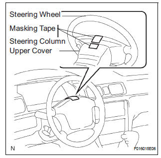
(1) Apply masking tape to the top center of the steering wheel and steering column upper cover.
(2) Drive the vehicle in a straight line for 100 meters at a constant speed of 35 mph (56 km/ h), and hold the steering wheel to maintain the course.
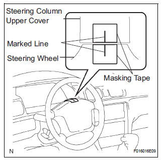
(3) Draw a line on the masking tape as shown in the illustration.
(4) Turn the steering wheel to its straight position.
HINT: Refer to the upper surface of the steering wheel, steering spoke and SRS airbag line for the straight position.
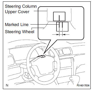
(5) Draw a new line on the masking tape or the steering wheel as shown in the illustration.
(6) Measure the distance between the 2 lines on the masking tape of the steering wheel.
(7) Convert the measured distance to steering angle.
HINT:
- Measured distance 1 mm (0.04 in.) = Steering angle approximately 1 deg.
- Make a note of the steering angle.
(b) Adjust the steering angle.
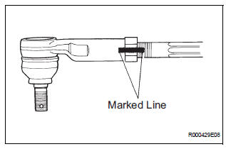
(1) Draw a line on the RH and LH tie rod and on the RH and LH rack end, which can easily be seen.
(2) Using a paper gauge, measure the distance from the RH and LH tie rod ends to the rack end screws.
HINT:
- Measure the RH side and LH side.
- Make a note of the measured values.
(3) Remove the RH and LH boot clips from the rack boots.
(4) Loosen the RH and LH lock nuts.
(5) Turn the RH and LH rack end by the same amount (but in different directions) according to the steering angle.
HINT: 1 turn 360 deg. of rack end (1.5 mm (0.059 in.) horizontal movement) - 12 deg. of steering angle.
(6) Tighten the RH and LH lock nuts.
Torque: 74 N*m (755 kgf*cm, 55 ft.*lbf)
NOTICE:
Make sure that the difference in length between RH and LH tie rod ends and rack end screws are within 1.5 mm (0.059 in.).
(7) Install the RH and LH boot clips.
 On-vehicle Inspection
1. CHECK STEERING WHEEL FREEPLAY
(a) Stop the vehicle and face the tires straight ahead.
(b) Rock the steering wheel gently up and down with
your hand, check the steering wheel freeplay.
Max ...
 Steering Column Assembly
COMPONENTS
...
Other materials:
Short to GND in Front Passenger Side Squib
2nd Step Circuit
DTC B1187/55 Short to GND in Front Passenger Side Squib
2nd Step Circuit
DESCRIPTION
The front passenger side squib 2nd step circuit consists of the center airbag
sensor assembly and the
front passenger airbag assembly.
The circuit instructs the SRS to deploy when deployment conditions are ...
Only Wireless Door Lock Control Function does not Operate
DESCRIPTION
The door control receiver receives a signal from the transmitter and sends
this signal to the multiplex
network body ECU. Then, the multiplex network body ECU controls operation of the
door locks and power
windows.
Then, the power slide door ECU causes the power slide door to o ...
Manual Up / Down and Auto Down Function does not Operate on
Passenger Side Only
DESCRIPTION
If the manual UP/DOWN function does not operate, the power window motor, the
regulator switch or the
wire harness may be malfunctioning.
WIRING DIAGRAM
INSPECTION PROCEDURE
1 CHECK WIRE HARNESS (POWER SOURCE)
Disconnect the P37 regulator switch connector.
Turn ...
