Toyota Sienna Service Manual: Adjustment
HINT:
- On the RH side, use the same procedures as on the LH side.
- Since a centering bolt is used as door hinge mounting bolts on the body side and the door side, the door cannot be adjusted with them on. Substitute a bolt with a washer for the centering bolt.
1. INSPECT BACK DOOR PANEL SUB-ASSEMBLY
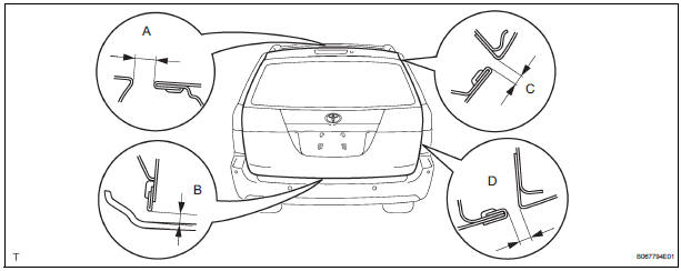
- Check that the clearance is within the standard range.
Standard

2. ADJUST BACK DOOR PANEL SUB-ASSEMBLY
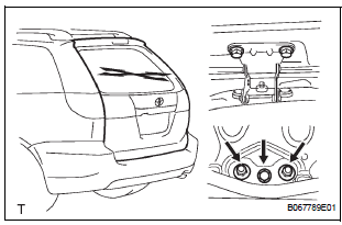
- Adjust the door forward / rearward and vertically by loosening the body side hinge nuts and bolt.
- Tighten the body side hinge nuts and bolt after the
adjustment.
Torque: 19.5 N*m (200 kgf*cm, 14 ft.*lbf)
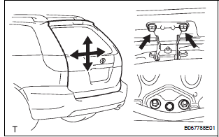
- Horizontally and vertically adjust the door by loosening the door side hinge bolts.
- Tighten the body side hinge bolts after the
adjustment.
Torque: 19.5 N*m (200 kgf*cm, 14 ft.*lbf)
- Using a screwdriver, remove the back door scuff plate.
HINT: Tape the screwdriver tip before use.
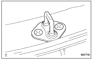
- Adjust the striker position by slightly loosening the striker mounting screws and hitting the striker with a plastic-faced hammer.
- Tighten the striker mounting screws after the
adjustment.
Torque: 27 N*m (275 kgf*cm, 20 ft.*lbf)
 Disassembly
1. REMOVE BACK DOOR GARNISH CENTER
Using a clip remover, disengage the 5 clips and
remove the garnish center.
2. REMOVE BACK DOOR SIDE GARNISH LH
Using a clip remover, disengage the 3 ...
 Reassembly
1. INSTALL BACK DOOR STOPPER LOWER
Install the 2 stoppers with the 4 bolts.
Torque: 7.0 N*m (71 kgf*cm, 62 in.*lbf)
2. INSTALL BACK DOOR BASE STOPPER BRACKET
Install the 2 stopper bracket ...
Other materials:
All Doors cannot be Locked / Unlocked at Once
DESCRIPTION
The body ECU receives a switch signal from the master switch, the door
control switch, the driver door
key cylinder and the passenger door key cylinder and then drives the door lock
motor.
WIRING DIAGRAM
INSPECTION PROCEDURE
1 INSPECT FUSE (ECU-B)
Remove ECU-B fuse f ...
Steering Pad Switch Circuit
DESCRIPTION
This circuit sends an operation signal from the steering pad switch to the
radio receiver.
If there is an open in the circuit, the navigation system cannot be operated
using the steering pad switch.
If there is a short in the circuit, the resulting condition is the same as if ...
Typical DOT and Tire Identification Number (TIN)
DOT symbol*
Tire Identification Number (TIN)
Tire manufacturerŌĆÖs identification
mark
Tire size code
ManufacturerŌĆÖs optional tire
type code (3 or 4 letters)
Manufacturing week
Manufacturing year
*: The DOT symbol certifies that the tire conforms to applicable Federal
Mo ...
