Toyota Sienna Service Manual: Door LOCK Position Circuit
DESCRIPTION
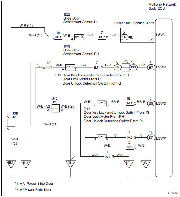
This circuit detects the state of the door lock detection sensor and send it to the Multiplex network body ECU.
WIRING DIAGRAM
INSPECTION PROCEDURE
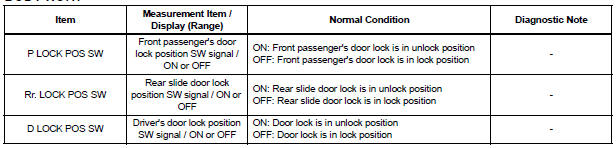
1 READ VALUE OF INTELLIGENT TESTER
- Connect the intelligent tester to DLC3.
- Turn the ignition switch ON and push the intelligent tester main switch ON.
- Select the items below in the DATA LIST, and read the displays on the intelligent tester.
BODY NO.1:
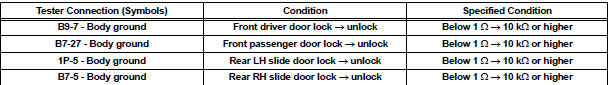
2 CHECK HARNESS AND CONNECTOR
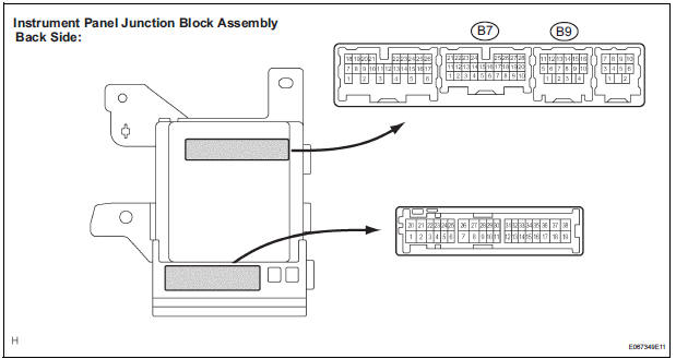
- Disconnect the 1P, B7 and B9 connector from instrument panel junction block assembly.
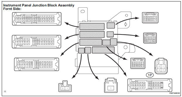
- Check the continuity between each of the terminals of the instrument panel junction block assembly connector side and body ground as shown in the chart below.
Resistance
GO TO POWER DOOR LOCK CONTROL SYSTEM
 Door Courtesy Switch Circuit
DESCRIPTION
The Multiplex network body ECU detects the condition of the door courtesy
switch assembly.
WIRING DIAGRAM
INSPECTION PROCEDURE
1 READ VALUE OF INTELLIGENT TESTER
Connect the ...
 Illumination Circuit
DESCRIPTION
The Multiplex network body ECU controls illumination light as shown in the
chart below.
Room light assembly (Interior light, luggage component light) and
courtesy light wit ...
Other materials:
Maintenance data
(fuel, oil level, etc.)
Dimensions and weights
*1: Unladen vehicle
*2: The model code is indicated on the Certification Label. For details, see
“Vehicle identification” below.
*3: The towing package is required.
Toyota does not recommend towing with this vehicle without the towing
package.
Vehicle identifi ...
Installation
1. Install transmission valve body assembly
(a) Install the shift solenoid valve SL1 to the valve body
assembly with the bolt.
Torque: 6.6 N*m (67 kgf*cm, 58 in.*lbf)
(b) Install the shift solenoid valve SL2 to the valve body
assembly with the bolt.
Torque: 11 N*m (110 kgf*cm, 8 ft ...
If your vehicle overheats
The following may indicate that your vehicle is overheating.
The needle of the engine coolant temperature gauge
enters the red zone or a loss of engine power is experienced. (For
example, the vehicle speed does not increase.)
The warning message indicating overheats is shown on the
mult ...
