Toyota Sienna Service Manual: Door Courtesy Switch Circuit
DESCRIPTION
The Multiplex network body ECU detects the condition of the door courtesy switch assembly.
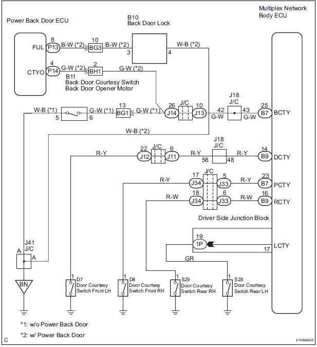
WIRING DIAGRAM
INSPECTION PROCEDURE
1 READ VALUE OF INTELLIGENT TESTER
- Connect the intelligent tester to DLC3.
- Turn the ignition switch to ON and push the intelligent tester main switch ON.
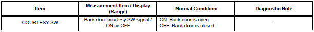
- Select the items below in the DATA LIST, and read the displays on the intelligent tester
BODY NO.1:
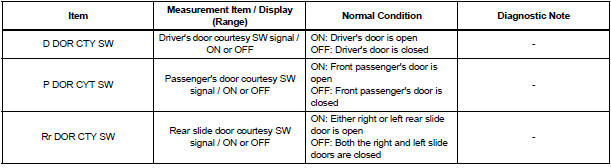
BACK DOOR:
2 INSPECT COURTESY LIGHT SWITCH
- Inspect each of the courtesy light switch continuity
3 INSPECT BACK DOOR LOCK ASSEMBLY
- Inspect the courtesy light switch terminal of the back door lock assembly
4 CHECK HARNESS AND CONNECTOR
- Disconnect the 1P, B7 and B9 connector from the instrument panel junction block assembly
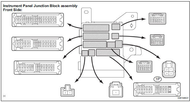
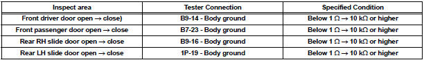
- Check the resistance between each of the terminals of instrument panel junction block assembly connector side and body ground as shown in the chart below.
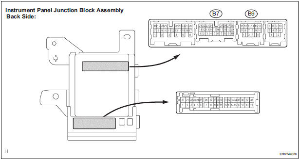
Resistance
5 INSPECT INSTRUMENT PANEL JUNCTION BLOCK ASSEMBLY (BACK DOOR COURTESY LIGHT SWITCH CIRCUIT)
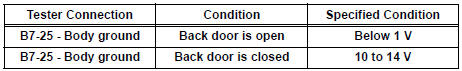
- Measure voltage between the terminal B7-25 of the multiplex network body ECU and body ground.
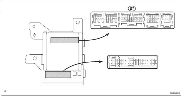
Voltage
6 CONFIRM VEHICLE TYPE
- Check the vehicle models.
A: w/o Power back door
B: w/ Power back door
7 INSPECT POWER BACK DOOR SYSTEM
- Inspect the power back door circuit
REPAIR OR REPLACE HARNESS OR CONNECTOR
 Automatic Light Control Sensor Circuit
DESCRIPTION
The Multiplex network body ECU receives the signal from the automatic light
control sensor.
HINT:
DTC code is output when malfunction of automatic light control sensor or open or
...
 Door LOCK Position Circuit
DESCRIPTION
This circuit detects the state of the door lock detection sensor and send it
to the Multiplex network body
ECU.
WIRING DIAGRAM
INSPECTION PROCEDURE
1 READ VALUE OF INTELLIGENT T ...
Other materials:
Installation
HINT:
Install the RH side by the same procedure as the LH side.
1. INSTALL REAR DISC BRAKE CYLINDER MOUNTING
LH
(a) Install the rear disc brake cylinder mounting LH with
the 2 bolts.
Torque: 88 N*m (900 kgf*cm, 65 ft.*lbf)
2. INSTALL REAR DISC BRAKE PAD SUPPORT PLATE
(a) Install the rear d ...
Removal
1. REMOVE REAR DOOR SCUFF PLATE
2. REMOVE REAR DOOR WEATHERSTRIP
3. REMOVE BACK DOOR WEATHERSTRIP
4. REMOVE BACK DOOR SCUFF PLATE
5. REMOVE FRONT QUARTER TRIM PANEL ASSEMBLY
Remove the floor anchor cover.
Remove the bolt and disconnect the No. 2 rear seat
outer belt assem ...
Inspection and adjustment procedure
Tire valve
Tire pressure gauge
Remove the tire valve cap.
Press the tip of the tire pressure gauge onto the tire valve.
Read the pressure using the gauge gradations.
If the tire inflation pressure is not at the recommended level, adjust
the pressure.
If you add too much air, ...
