Toyota Sienna Service Manual: Illumination Circuit
DESCRIPTION
The Multiplex network body ECU controls illumination light as shown in the chart below.
- Room light assembly (Interior light, luggage component light) and courtesy light with DOOR position
- Map light assembly (Personal light)
- Transponder key amplifier (Ignition key cylinder light)
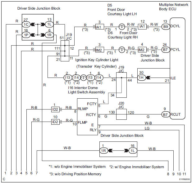
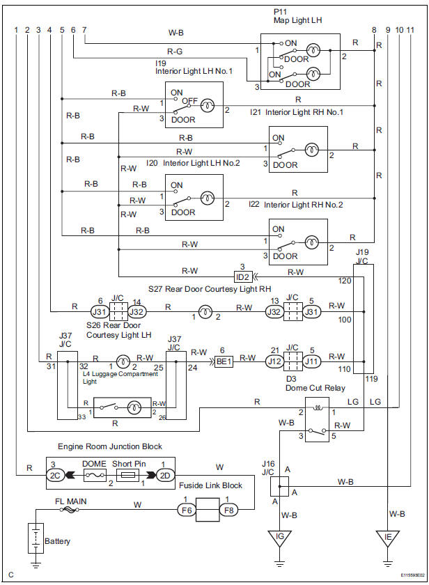
WIRING DIAGRAM
INSPECTION PROCEDURE
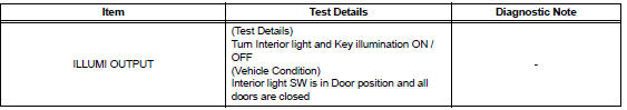
1 PERFORM ACTIVE TEST BY INTELLIGENT TESTER
- Connect the intelligent tester to DLC3.
- Turn the ignition switch ON and push the intelligent tester main switch ON.
- Select the item below in the ACTIVE TEST and then check that the relay operates
DATA LIST / AIR CONDITIONER
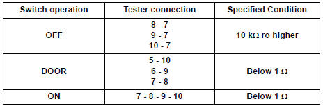
2 INSPECT LIGHT CONTROL RELAY
- Check that there is resistance between the terminals at each switch position as shown in the chart.
Resistance
3 INSPECT INTERIOR DOME LIGHT SWITCH ASSEMBLY
- Inspect interior dome light relay continuity.
Resistance
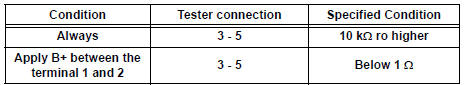
4 INSPECT INTERIOR LIGHT
- Inspect the each of interior light
5 INSPECT INSTRUMENT PANEL JUNCTION BLOCK ASSEMBLY
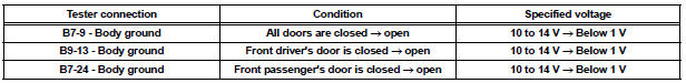
- Measure voltage between each of the terminals as shown in the chart below
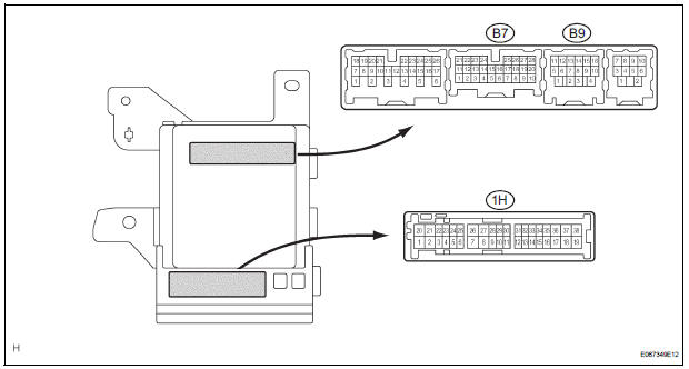
Voltage

PROCEED TO NEXT CIRCUIT INSPECTION SHOWN IN PROBLEM SYMPTOMS TABLE
 Door LOCK Position Circuit
DESCRIPTION
This circuit detects the state of the door lock detection sensor and send it
to the Multiplex network body
ECU.
WIRING DIAGRAM
INSPECTION PROCEDURE
1 READ VALUE OF INTELLIGENT T ...
 Parking Brake Switch Circuit
DESCRIPTION
The Multiplex network body ECU receives parking brake switch signal.
WIRING DIAGRAM
INSPECTION PROCEDURE
1 READ VALUE OF INTELLIGENT TESTER
Connect the intelligent tester to DL ...
Other materials:
Problem symptoms table
POWER WINDOW CONTROL SYSTEM (W/O JAM PROTECTION)
Symptom
Suspected Area
All power windows do not operate
PWR fuse
Power window relay (Marking: P/W)
Ignition switch
Power window regulator master switch
Power window regulator motor assembly
...
CD Player Mechanical Error/ CD Insertion and Ejection Error/ CD Reading
Abnormal/ CD Changer Mechanical Error/ CD Insertion and Ejection Error/ CD
Reading Abnormal
DTC 62-10 CD Player Mechanical Error
DTC 62-11 CD Insertion and Ejection Error
DTC 62-12 CD Reading Abnormal
DTC 63-10 CD Changer Mechanical Error
DTC 63-11 CD Insertion and Ejection Error
DTC 63-12 CD Reading Abnormal
DESCRIPTION
DTC No.
DTC Detecting Condition
Troub ...
Open in Front Pretensioner Squib RH Circuit
DTC B0131/64 Open in Front Pretensioner Squib RH Circuit
DESCRIPTION
The front pretensioner squib RH circuit consists of the center airbag sensor
assembly and the front seat
outer belt assembly RH.
This circuit instructs the SRS to deploy when deployment conditions are met.
DTC B0131/64 i ...
