Toyota Sienna Service Manual: DTC check / clear
1. CHECK DTC
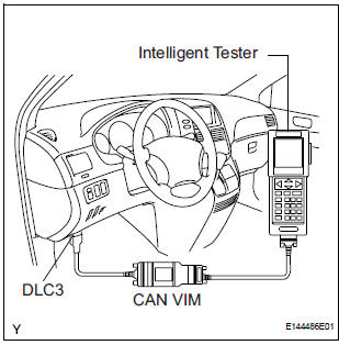
- Connect the intelligent tester to the DLC3.
- Connect the intelligent tester to the Controller Area Network Vehicle Interface Module (CAN VIM). Then connect the CAN VIM to the Data Link Connector 3 (DLC3).
- Turn the ignition switch to the ON position.
- Read the DTCs by following the prompts on the tester screen.
HINT: Refer to the intelligent tester operator's manual for further details.
2. CLEAR DTC
- Connect the intelligent tester to the DLC3.
- Turn the ignition switch to the ON position.
- Operate the intelligent tester to erase the codes.
HINT: Refer to the intelligent tester operator's manual for further details.
 Diagnosis system
1. DIAGNOSIS FUNCTION
The diagnosis function makes the light and the
multi-information display come on, and the CRUISE
main indicator light blink as shown in the illustration.
When ...
 Fail-safe chart
1. AUTO CANCEL FUNCTION (FAIL-SAFE FUNCTION):
HINT:
If a system malfunction occurs, the applicable DTCs will
appear on the multi-information display. In some cases,
a DTC will be set due to we ...
Other materials:
Microphone Circuit between Microphone and Radio and Navigation
Assembly
DESCRIPTION
This circuit sends a microphone signal from the microphone to the radio and
navigation assembly.
It also supplies power from the radio and navigation assembly to the microphone.
WIRING DIAGRAM
INSPECTION PROCEDURE
1 INSPECT RADIO AND NAVIGATION ASSEMBLY
Measure the v ...
Brake Switch
DTC P0504 Brake Switch "A" / "B" Correlation
DTC P0724 Brake Switch "B" Circuit High
DESCRIPTION
The stop light switch is a duplex system that transmits two signals: STP and
ST1-. These two signals are
used by the ECM to monitor whether or not the brake system is ...
Master Error
DTC 01-DF Master Error
DESCRIPTION
DTC No.
DTC Detection Condition
Trouble Area
01-DF
*1
The device with a display fails and the master is
switched to the audio device.
Also when a communication error between sub-master
(audio) and master occu ...
