Toyota Sienna Service Manual: ECM Communication Stop Mode
DESCRIPTION
|
Detection Item |
Symptom |
Trouble Area |
| ECM Communication Stop Mode |
|
|
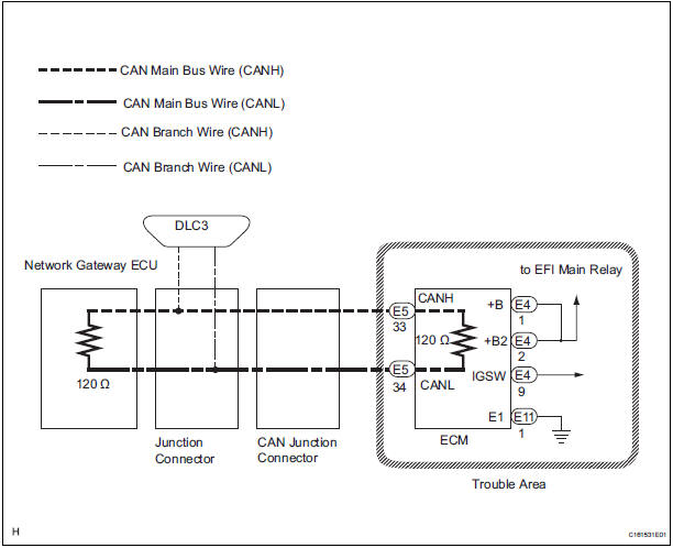
WIRING DIAGRAM
INSPECTION PROCEDURE
NOTICE:
- Turn the ignition switch off before measuring the resistances of CAN bus main wires and CAN bus branch wires.
- After the ignition switch is turned off, check that the key reminder warning system and light reminder warning system are not in operation.
- Before measuring the resistance, leave the vehicle as is for at least 1 minute and do not operate the ignition switch, any other switches, or the doors. If any doors need to be opened in order to check connectors, open the doors and leave them open.
HINT: Operating the ignition switch, any switches, or any doors triggers related ECU and sensor communication with the CAN. This communication will cause the resistance value to change.
1 CHECK OPEN IN CAN BUS WIRE (ECU MAIN BUS WIRE)
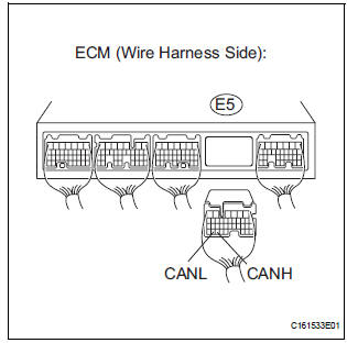
- Disconnect ECM connector (E5).
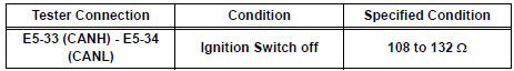
- Measure the resistance according to the value(s) in the table below.
Standard resistance
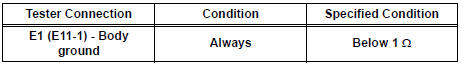
2 CHECK WIRE HARNESS (E1, BATT, +BM, IGSW)
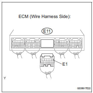
- Disconnect the ECM connector (E11).
- Measure the resistance according to the value(s) in the table below.
Standard resistance
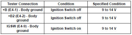
- Disconnect the ECM connector (E4).
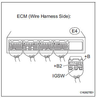
- Measure the voltage according to the value(s) in the table below.
Standard voltage
REPLACE ECM
 Yaw Rate Sensor Communication Stop Mode
DESCRIPTION
Detection Item
Symptom
Trouble Area
Yaw Rate Sensor
Communication Stop
Mode
"Yaw rate/ Deceleration sensor" is not displayed ...
 CAN Bus Line
DESCRIPTION
When any DTC for the CAN communication system is output, first measure the
resistance between the
terminals of the DLC3 to specify the trouble area, and check that there is no
short ...
Other materials:
Right Rear Wheel Speed Sensor Signal
DESCRIPTION
Refer to DTCs C0200/31, C0205/32, C1235/35 and C1236/36 (See page BC-92).
HINT:
DTC C0210/33 and C1238/38 are for the right rear speed sensor.
DTC C0215/34 and C1239/39 are for the left rear speed sensor.
WIRING DIAGRAM
INSPECTION PROCEDURE
1 READ VALUE ON INTELL ...
Evaporative Emission System Switching Valve Control Circuit High
DTC SUMMARY
DESCRIPTION
The circuit description can be found in the EVAP (Evaporative Emission)
System (See page ES-404).
INSPECTION PROCEDURE
Refer to the EVAP System (See page ES-404).
MONITOR DESCRIPTION
5 hours*1 after the ignition switch is turned off, the electric vacuum pump
...
Initialization
1. ZERO POINT CALIBRATION
NOTICE:
Make sure that the front passenger seat is not
occupied before performing the operation.
HINT:
Perform the zero point calibration and sensitivity check if
any of the following conditions occur.
The occupant classification ECU is replaced.
Acc ...
