Toyota Sienna Service Manual: Yaw Rate Sensor Communication Stop Mode
DESCRIPTION
|
Detection Item |
Symptom |
Trouble Area |
| Yaw Rate Sensor Communication Stop Mode |
|
|
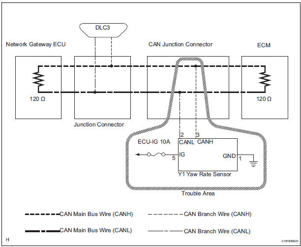
WIRING DIAGRAM
INSPECTION PROCEDURE
NOTICE:
- Turn the ignition switch off before measuring the resistances of CAN bus main wires and CAN bus branch wires.
- After the ignition switch is turned off, check that the key reminder warning system and light reminder warning system are not in operation.
- Before measuring the resistance, leave the vehicle as is for at least 1 minute and do not operate the ignition switch, any other switches, or the doors. If any doors need to be opened in order to check connectors, open the doors and leave them open.
HINT: Operating the ignition switch, any switches, or any doors triggers related ECU and sensor communication with the CAN. This communication will cause the resistance value to change.
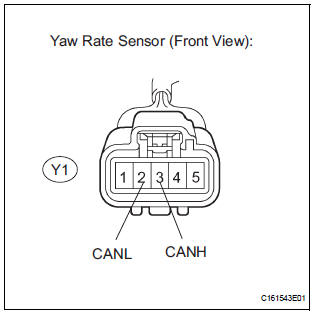
1 CHECK OPEN IN CAN BUS WIRE (YAW RATE SENSOR BRANCH WIRE)
- Turn the ignition switch off.
- Disconnect the yaw rate sensor connector.
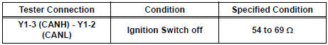
- Measure the resistance according to the value(s) in the table below.
Standard resistance
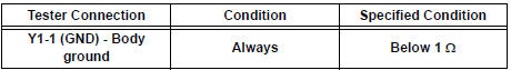
2 CHECK WIRE HARNESS (IG, GND)
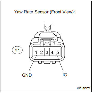
- Measure the resistance according to the value(s) in the table below.
Standard resistance
- Measure the voltage according to the value(s) in the table below.
Standard voltage
REPLACE YAW RATE SENSOR
 Steering Angle Sensor Communication Stop Mode
DESCRIPTION
Detection Item
Symptom
Trouble Area
Steering Angle Sensor
Communication Stop
Mode
"Steering angle sensor" is not displayed on ...
 ECM Communication Stop Mode
DESCRIPTION
Detection Item
Symptom
Trouble Area
ECM Communication Stop
Mode
"Engine" is not displayed on the "Communication
Bus Che ...
Other materials:
Lock Switch Circuit
DESCRIPTION
Each of the left and right seats has lock switches that detect the lock
condition of the seat legs to the floor
when the seat is in the original or folded-down state. If any of the lock
switches detect an unlock condition,
the 3rd SEAT indicator on the combination meter will come ...
Rear Occupant Classification Sensor LH Collision
Detection
DTC B1787 Rear Occupant Classification Sensor LH Collision
Detection
DESCRIPTION
DTC B1787 is output when the occupant classification ECU receives a collision
detection signal sent by
the rear occupant classification sensor LH if an accident occurs.
DTC B1787 is also output when the front s ...
Room temperature sensor
On-vehicle inspection
1. INSPECT A/C ROOM TEMPERATURE SENSOR
(a) Remove the A/C room temperature sensor.
(b) Measure the resistance according to the value(s) in
the table below.
Standard resistance
NOTICE:
Even slightly touching the sensor may
change the resistance value. Be sure ...
