Toyota Sienna Service Manual: Front Occupant Classification Sensor RH Collision Detection
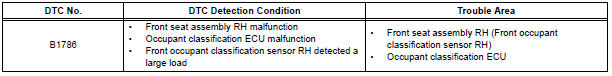
DTC B1786 Front Occupant Classification Sensor RH Collision Detection
DESCRIPTION
DTC B1786 is output when the occupant classification ECU receives a collision detection signal sent by the front occupant classification sensor RH if an accident occurs.
DTC B1786 is also output when the front seat assembly RH is subjected to a strong impact, even if an actual accident does not occur.
However, when the occupant classification ECU outputs a collision detection signal, even if the vehicle is not in a collision, DTC B1786 can be cleared by "Zero point calibration" and "Sensitivity check".
Therefore, if DTC B1786 is output, first perform "Zero point calibration" and "Sensitivity check".
WIRING DIAGRAM
INSPECTION PROCEDURE
1 PERFORM ZERO POINT CALIBRATION
- Connect the intelligent tester to the DLC3.
- Turn the ignition switch to the ON position.
- Using the intelligent tester, perform "Zero point calibration".
OK: "COMPLETED" is displayed.
2 PERFORM SENSITIVITY CHECK
- Using the intelligent tester, perform "Sensitivity check".
Standard value: 27 to 33 kg (59.52 to 72.75 lb)
3 CHECK DTC
- Turn the ignition switch to the ON position.
- Clear the DTCs stored in the memory
HINT: First clear DTCs stored in the occupant classification ECU and then in the center airbag sensor assembly. - Turn the ignition switch to the LOCK position.
- Turn the ignition switch to the ON position.
- Check the DTCs.
OK: DTC B1786 is not output.
HINT: Codes other than DTC B1786 may be output at this time, but they are not related to this check.
4 REPLACE FRONT SEAT ASSEMBLY RH
- Turn the ignition switch to the LOCK position.
- Disconnect the negative (-) terminal cable from the battery, and wait for at least 90 seconds.
- Replace the front seat assembly RH ( for flat type, SE-48 for manual seat, SE-58 for power seat).
HINT: Perform the inspection using parts from a normal vehicle if possible.
5 PERFORM ZERO POINT CALIBRATION
- Connect the negative (-) terminal cable to the battery.
- Connect the intelligent tester to the DLC3.
- Turn the ignition switch to the ON position.
- Using the intelligent tester, perform "Zero point calibration".
OK: "COMPLETED" is displayed.
6 PERFORM SENSITIVITY CHECK
- Using the intelligent tester, perform "Sensitivity check".
Standard value: 27 to 33 kg (59.52 to 72.75 lb)
7 CHECK DTC
- Turn the ignition switch to the ON position.
- Clear the DTCs stored in the memory.
HINT: First clear DTCs stored in the occupant classification ECU and then in the center airbag sensor assembly.
- Turn the ignition switch to the LOCK position.
- Turn the ignition switch to the ON position.
- Check the DTCs.
OK: DTC B1786 is not output.
HINT: Codes other than DTC B1786 may be output at this time, but they are not related to this check
8 REPLACE OCCUPANT CLASSIFICATION ECU
- Turn the ignition switch to the LOCK position.
- Disconnect the negative (-) terminal cable from the battery, and wait for at least 90 seconds.
- Replace the occupant classification ECU
9 PERFORM ZERO POINT CALIBRATION
- Connect the negative (-) terminal cable to the battery.
- Connect the intelligent tester to the DLC3.
- Turn the ignition switch to the ON position.
- Using the intelligent tester, perform "Zero point calibration".
OK: "COMPLETED" is displayed.
10 PERFORM SENSITIVITY CHECK
- Using the intelligent tester, perform "Sensitivity check".
Standard value: 27 to 33 kg (59.52 to 72.75 lb)
END
 Front Occupant Classification Sensor LH Collision
Detection
Front Occupant Classification Sensor LH Collision
Detection
DTC B1785 Front Occupant Classification Sensor LH Collision
Detection
DESCRIPTION
DTC B1785 is output when the occupant classification ECU receives a collision
detection signal sent by
the front ...
 Rear Occupant Classification Sensor LH Collision
Detection
Rear Occupant Classification Sensor LH Collision
Detection
DTC B1787 Rear Occupant Classification Sensor LH Collision
Detection
DESCRIPTION
DTC B1787 is output when the occupant classification ECU receives a collision
detection signal sent by
the rear o ...
Other materials:
Selecting the audio
source
Switching between audio sources such as radio and CD are
explained in this section.
Changing audio source
Press the “AUDIO” button to display the audio source selection
screen.
If the audio source selection screen is not displayed, press the “AUDIO”
button again.
Select the des ...
Installation
1. TEMPORARILY TIGHTEN AIR CONDITIONING UNIT ASSEMBLY
(a) Engage the 2 claws.
(b) Temporarily tighten the air conditioning unit
assembly with the nut.
Torque: 9.8 N*m (100 kgf*cm, 87 in.*lbf)
2. INSTALL LOWER DEFROSTER NOZZLE ASSEMBLY
(a) Engage the 4 claws and install the lower defr ...
Brake Switch "A" Circuit
DTC P0571 Brake Switch "A" Circuit
DESCRIPTION
When the brake pedal is depressed, the stop light switch sends a signal to
the ECM. When the ECM
receives this signal, it cancels the cruise control. The fail-safe function
operates to enable normal driving
even if there is a malfuncti ...
