Toyota Sienna Service Manual: CAN Bus Line
DESCRIPTION
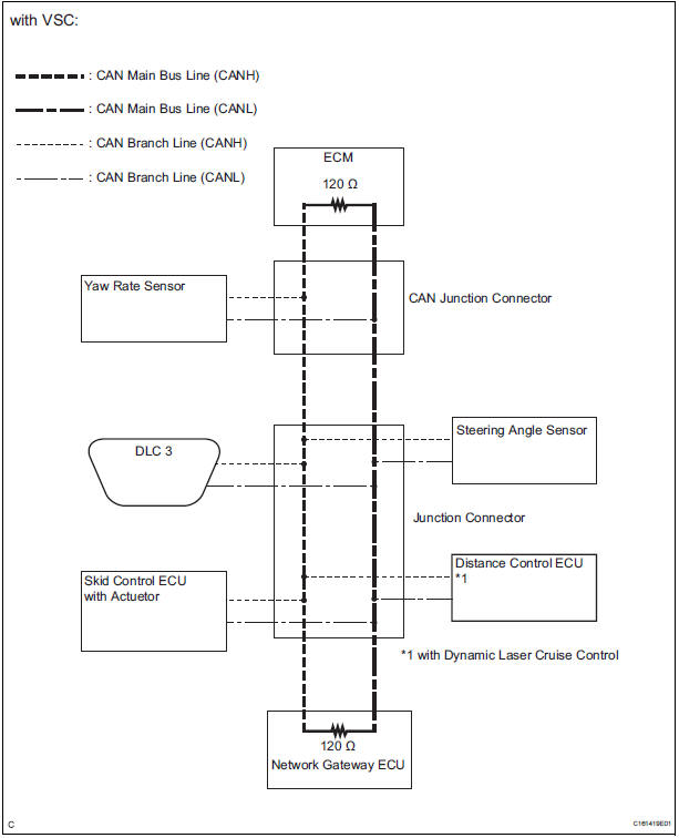
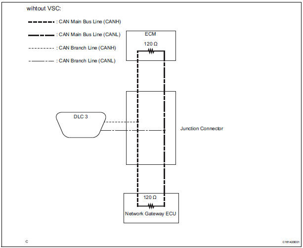
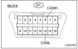
When any DTC for the CAN communication system is output, first measure the resistance between the terminals of the DLC3 to specify the trouble area, and check that there is no short in the CAN main wire, between the main wire, and +B or GND.
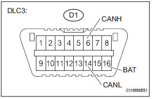
WIRING DIAGRAM
INSPECTION PROCEDURE
NOTICE:
- Turn the ignition switch off before measuring the resistances of CAN bus main wires and CAN bus branch wires.
- After the ignition switch is turned off, check that the key reminder warning system and light reminder warning system are not in operation.
- Before measuring the resistance, leave the vehicle as is for at least 1 minute and do not operate the ignition switch, any other switches, or the doors. If any doors need to be opened in order to check connectors, open the doors and leave them open.
HINT: Operating the ignition switch, any switches, or any doors triggers related ECU and sensor communication with the CAN. This communication will cause the resistance value to change.
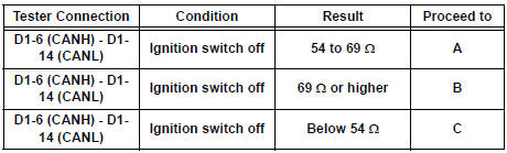
1 CHECK CAN BUS WIRE (MAIN WIRE FOR DISCONNECTION, CAN BUS LINES FOR SHORT CIRCUIT)
- Turn the ignition switch off.
- Measure the resistance according to the value(s) in the table below.
Standard resistance
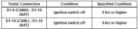
2 CHECK FOR SHORT TO B+ IN CAN BUS WIRE
- Measure the resistance according to the value(s) in the table below.
Standard resistance
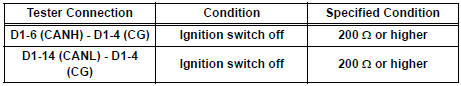
3 CHECK FOR SHORT TO GND IN CAN BUS WIRE
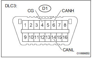
- Measure the resistance according to the value(s) in the table below.
Standard resistance
GO TO HOW TO PROCEED WITH TROUBLESHOOTING
 ECM Communication Stop Mode
DESCRIPTION
Detection Item
Symptom
Trouble Area
ECM Communication Stop
Mode
"Engine" is not displayed on the "Communication
Bus Che ...
 Open in CAN Main Bus Line
DESCRIPTION
There may be an open circuit in the CAN main bus wire and/or the DLC3 branch
wire when the resistance
between terminals 6 (CANH) and 14 (CANL) of the DLC3 is 69 Ω or higher.
...
Other materials:
DTC check / clear
1. CHECK DTC (USING INTELLIGENT TESTER)
Checking DTCs.
Connect the intelligent tester to the DLC3.
Turn the ignition switch ON.
Read DTCs by following the prompts on the
tester screen.
HINT:
Refer to the intelligent tester operator's manual
for furthe ...
Rear Room Temperature Sensor Circuit
DESCRIPTION
This sensor detects the rear cabin temperature that is used as the basis for
temperature control and
sends a signal to the A/C amplifier.
WIRING DIAGRAM
INSPECTION PROCEDURE
1 READ VALUE OF INTELLIGENT TESTER
(a) Connect the intelligent tester to the DLC3.
(b) Turn the ign ...
Air Inlet Damper Control Servo Motor Circuit
DESCRIPTION
The air inlet control servo motor is controlled by the A/C amplifier and
moved to the desired position.
The air inlet control servo motor switches the air inlet mode by rotating
(normal, reverse) with electrical
power from the A/C amplifier. This controls intake air and changes ...
