Toyota Sienna Service Manual: ECM Power Source Circuit
DESCRIPTION
When the ignition switch is turned to the ON position, the battery voltage is applied to terminal IGSW of the ECM. The ECM MREL output signal causes a current to flow to the coil, closing the contacts of the EFI relay and supplying power to terminal +B of the ECM.
If the ignition switch is turned off, the ECM holds the EFI relay ON for a maximum of 2 seconds to allow for the initial setting of the throttle valve.
WIRING DIAGRAM

INSPECTION PROCEDURE
1 INSPECT ECM (+B VOLTAGE)
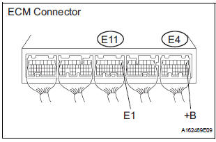
- Turn the ignition switch to the ON position.
- Measure the voltage according to the value(s) in the table below.
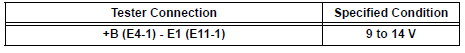
Standard voltage
2 CHECK HARNESS AND CONNECTOR (ECM - BODY GROUND)
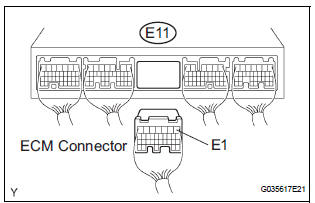
- Disconnect the E11 ECM connector.
- Measure the resistance according to the value(s) in the table below.
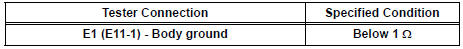
Standard resistance: Check for open
- Reconnect the ECM connector.
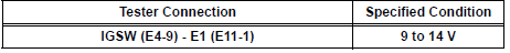
3 INSPECT ECM (IGSW VOLTAGE)
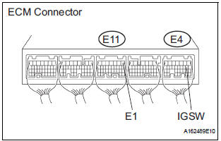
- Turn the ignition switch to the ON position.
- Measure the voltage according to the value(s) in the table below.
Standard voltage
4 CHECK FUSE (IGN FUSE)
- Remove the IGN fuse from the driver side junction block.
- Measure the IGN fuse resistance.
Standard resistance: Below 1 Ω
- Reinstall the IGN fuse.
5 CHECK HARNESS AND CONNECTOR (IGNITION SWITCH - ECM)

- Disconnect the E4 ECM connector.
- Disconnect the I15 ignition switch connector.
- Measure the resistance according to the value(s) in the table below.
Standard resistance: Check for open
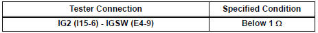
Check for short
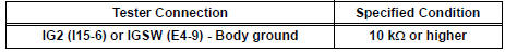
- Reconnect the ECM connector.
- Reconnect the ignition switch connector.
6 INSPECT IGNITION SWITCH ASSEMBLY
- Inspect the ignition or starter switch assembly
7 CHECK FUSE (AM2 FUSE)
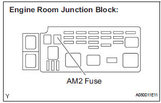
- Remove the AM2 fuse from the engine room junction block.
- Measure the resistance according to the value(s) in the
table below.
Standard resistance: Below 1 Ω
- Reinstall the AM2 fuse
REPAIR OR REPLACE HARNESS OR CONNECTOR (IGNITION SWITCH - BATTERY)
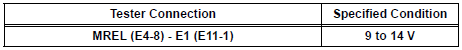
8 INSPECT ECM (MREL VOLTAGE)
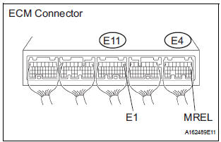
- Turn the ignition switch to the ON position.
- Measure the voltage according to the value(s) in the table below.
Standard voltage
9 CHECK FUSE (EFI NO.1 FUSE)
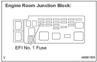
- Remove the EFI No. 1 fuse from the engine room junction block.
- Measure the EFI No. 1 fuse resistance.
Standard resistance: Below 1 Ω
- Reinstall the EFI No. 1 fuse.
10 INSPECT RELAY (EFI RELAY)
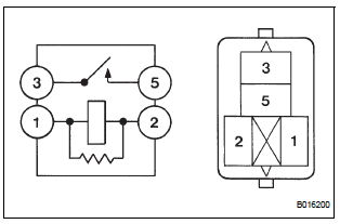
- Remove the EFI relay from the engine room junction block.
- Measure the EFI relay resistance.
Standard resistance
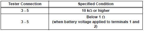
- Reinstall the EFI relay.
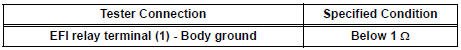
11 CHECK HARNESS AND CONNECTOR (EFI RELAY - ECM)
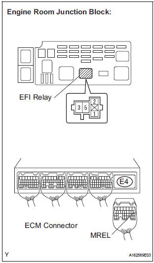
- Check the harness and connector between the EFI relay and ECM.
- Remove the EFI relay from the engine room junction block.
- Disconnect the E4 ECM connector.
- Measure the resistance according to the value(s) in the table below.
Standard resistance: Check for open
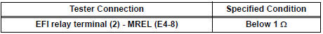
Check for short
12 CHECK HARNESS AND CONNECTOR (EFI RELAY - ECM)
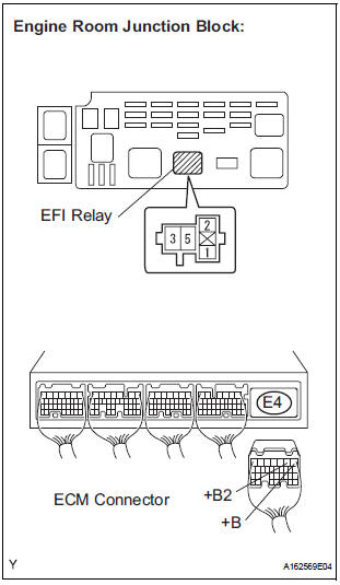
- Remove the EFI relay from the engine room junction block.
- Disconnect the E4 ECM connector.
- Measure the resistance according to the value(s) in the table below.
Standard resistance: Check for open

Check for short

- Reinstall the EFI relay.
- Reconnect the ECM connector.
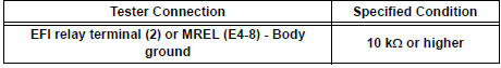
13 CHECK HARNESS AND CONNECTOR (EFI RELAY - BODY GROUND)

- Check the harness and connector between the EFI relay and body ground.
- Measure the resistance according to the value(s) in the table below.
Standard resistance : Check for open
- Reinstall the EFI relay.
- Reconnect the ECM connector.
REPAIR OR REPLACE HARNESS OR CONNECTOR (EFI RELAY - BATTERY)
 EVAP System
RELATED DTCS
If any EVAP system DTCs are set, the malfunctioning area can be determined
using the table below.
NOTICE:
If the 0.02 inch reference pressure difference between the first and ...
 VC Output Circuit
DESCRIPTION
The ECM constantly uses 5 V from the battery voltages supplied to the +B (BATT)
terminal to operate the
microprocessor. The ECM also provides this power to the sensors through the VC
...
Other materials:
Removal
1. REMOVE REAR SEAT LEG SIDE GARNISH SUBASSEMBLY RH
Disengage the clips and remove the seat leg side
garnish sub-assembly RH.
2. REMOVE REAR NO. 2 SEAT ASSEMBLY RH
Remove the bolt and locus cable RH.
Remove the 2 bolts and rear No. 2 seat assembly
RH.
R ...
Cargo net hooks
Raise the hook to use.
Pattern 1
Pattern 2
NOTICE
To prevent damage to the cargo net hooks, avoid hanging things other
than
a cargo net on them.
Storage box (if equipped)
Engage the latch buckle. ...
Throttle / Pedal Position Sensor / Switch "A"
Circuit Range / Performance Problem
DTC P0121 Throttle / Pedal Position Sensor / Switch "A"
Circuit Range / Performance Problem
HINT:
This DTC relates to the Throttle Position (TP) sensor.
DESCRIPTION
Refer to DTC P0120
DTC No.
DTC Detection Condition
Trouble Area
P0121
Differen ...
