Toyota Sienna Service Manual: Engine Hood Courtesy Switch Circuit
DESCRIPTION
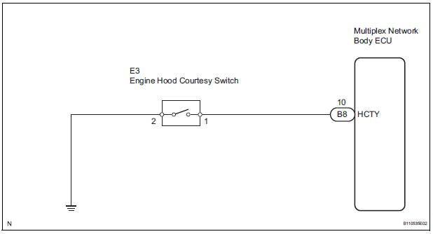
The engine hood courtesy switch is built in the engine hood lock assembly. The switch turns on when the engine hood is opened and turns off when the engine hood is closed.
WIRING DIAGRAM
INSPECTION PROCEDURE
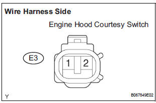
1 INSPECT ENGINE HOOD COURTESY SWITCH
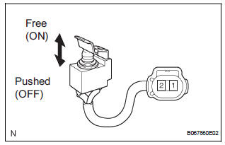
- Remove the courtesy switch.
- Disconnect the E3 switch connector.
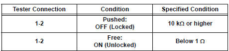
- Measure the resistance according to the value(s) in the table below.
Standard resistance
2 CHECK HARNESS AND CONNECTOR (MULTIPLEX NETWORK BODY ECU - ENGINE HOOD COURTESY SWITCH)
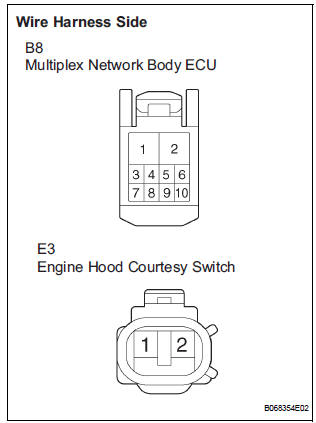
- Disconnect the B8 ECU connector.
- Measure the resistance according to the value(s) in the table below.
Standard resistance
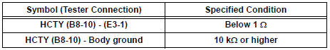
3 CHECK HARNESS AND CONNECTOR (ENGINE HOOD COURTESY SWITCH - BODY GROUND)
- Measure the resistance according to the value(s) in the table below.
Standard resistance
REPLACE MULTIPLEX NETWORK BODY ECU
 Terminals of ECU
1. CHECK INSTRUMENT PANEL J/B ASSEMBLY
(MULTIPLEX NETWORK BODY ECU)
Disconnect the B6, B7 and B9 ECU connectors.
Disconnect the 1A, 1C, 1L and 1K J/B connectors.
Measure t ...
 Security Horn Circuit
DESCRIPTION
During the alarm sounding state, the relay in the ECU turns on and off in a
cycle of approximately 0.2
seconds, causing the security horn to sound.
WIRING DIAGRAM
INSPECTION PROC ...
Other materials:
Reassembly
1. INSTALL REAR SEAT STAY SUB-ASSEMBLY
Install the seat stay sub-assembly with the nut.
Torque: 5.5 N*m (56 kgf*cm, 49 in.*lbf)
2. INSTALL NO. 2 SEAT CUSHION SPRING ASSEMBLY
RH
3. INSTALL LOCUS CABLE RH
Install the locus cable RH with the nut.
Torque: 5.5 N*m (56 kgf*cm, ...
Hood
Release the lock from the inside of the vehicle to open the hood.
Pull the hood lock release lever.
The hood will pop up slightly.
Pull up the auxiliary catch lever
and lift the hood.
Hold the hood open by inserting
the supporting rod into the slot
WARNING ...
Short to B+ in Driver Side Squib Circuit
DTC B0103/12 Short to B+ in Driver Side Squib Circuit
DESCRIPTION
The driver side squib circuit consists of the center airbag sensor assembly,
the spiral cable and the
steering pad.
The circuit instructs the SRS to deploy when deployment conditions are met.
DTC B0103/12 is recorded when a ...
