Toyota Sienna Service Manual: Terminals of ECU
1. CHECK INSTRUMENT PANEL J/B ASSEMBLY (MULTIPLEX NETWORK BODY ECU)
- Disconnect the B6, B7 and B9 ECU connectors.
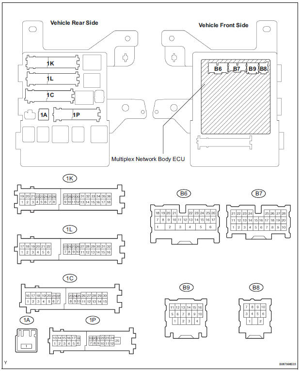
- Disconnect the 1A, 1C, 1L and 1K J/B connectors.
- Measure the voltage and resistance between each terminal of the wire harness side connectors and body ground
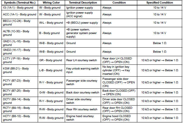
If the result is not as specified, there may be a malfunction on the wire harness side.
- Reconnect the B6, B7 and B9 ECU connectors.
- Reconnect the 1A, 1C, 1L and 1K J/B connectors.
- Measure the voltage between each terminal of the connectors and the body ground.
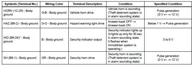
*: with Engine Immobiliser System If the result is not as specified, the J/B assembly (body ECU) may have a malfunction.
- Engine Hood Courtesy Switch Circuit
- Security Horn Circuit
- Ignition Switch Circuit
- Security Indicator Light Circuit
- ECU Power Source Circuit
 Problem symptoms table
Proceed to the reference page shown in the table below for
each malfunction symptom and troubleshoot each circuit.
HINT:
Troubleshooting of the theft deterrent system is based on the
premise tha ...
 Engine Hood Courtesy Switch Circuit
DESCRIPTION
The engine hood courtesy switch is built in the engine hood lock assembly.
The switch turns on when the
engine hood is opened and turns off when the engine hood is closed.
WIRING DIAG ...
Other materials:
Front Clearance Sonar Sensor RH Circuit
DESCRIPTION
An ultrasonic sensor consists of a sensor portion that transmits and receives
ultrasonic waves and a preamplifier
that amplifies them. The ultrasonic sensor outputs the ultrasonic waves and
sends the reveiced
signals to the clearance warning ECU.
WIRING DIAGRAM
INSPECTION PR ...
Installation
1. INSTALL HEATED OXYGEN SENSOR (for Bank 2
Sensor 2) (See page EC-39)
2. INSTALL FRONT EXHAUST PIPE ASSEMBLY
(a) Install a new gasket to the front exhaust pipe
assembly.
(b) Install the front exhaust pipe assembly with the 2
nuts.
Torque: 62 N*m (632 kgf*cm, 46 ft.*lbf)
3. V
V(A) ins ...
Air Outlet Damper Position Sensor Circuit
DESCRIPTION
This sensor detects the position of the air outlet control servo motor and
sends the appropriate signals to
the A/C amplifier. The position sensor is built in the air outlet control servo
motor. The position sensor's
resistance changes as the air outlet control servo motor arm ...
