Toyota Sienna Service Manual: Reassembly
1. INSTALL REAR SEAT STAY SUB-ASSEMBLY
- Install the seat stay sub-assembly with the nut.
Torque: 5.5 N*m (56 kgf*cm, 49 in.*lbf)
2. INSTALL NO. 2 SEAT CUSHION SPRING ASSEMBLY RH
3. INSTALL LOCUS CABLE RH
- Install the locus cable RH with the nut.
Torque: 5.5 N*m (56 kgf*cm, 49 in.*lbf)
4. INSTALL NO. 2 SEAT CUSHION COVER SUBASSEMBLY RH
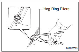
- Using hog ring pliers, install the No. 2 seat cushion cover sub-assembly RH to the seat cushion pad with new hog rings.
NOTICE:
- Be careful not to damage the cover.
- When installing the hog rings, take care to prevent wrinkles as much as possible.
5. INSTALL REAR SEAT LOCK RELEASE STRAP ASSEMBLY
- Install the rear seat lock release strap assembly with
the nut.
Torque: 5.5 N*m (56 kgf*cm, 49 in.*lbf)
6. INSTALL RECLINING ADJUSTER RELEASE HANDLE NO. 2 RH
- Install the reclining adjuster release handle No. 2
RH with the nut.
Torque: 5.5 N*m (56 kgf*cm, 49 in.*lbf)
7. INSTALL RECLINING RELEASE HANDLE SUBASSEMBLY RH
- Install the reclining release handle sub-assembly
RH with the nut.
Torque: 5.5 N*m (56 kgf*cm, 49 in.*lbf)
8. INSTALL REAR SEAT BACK CONNECTING RH WIRE
- Install the rear seat back connecting RH wire.
9. INSTALL NO. 2 SEATBACK COVER RH
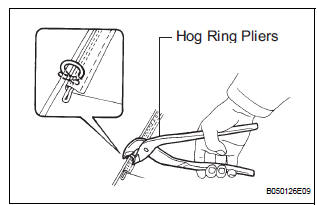
- Using hog ring pliers, install the No. 2 seatback cover RH to the seatback pad with new hog rings.
NOTICE:
- Be careful not to damage the cover.
- When installing the hog rings, take care to prevent wrinkles as much as possible.
- Install the 2 headrest supports.
10. INSTALL NO. 2 SEATBACK LOCK CONTROL BEZEL
- Install the No. 2 seatback lock control bezel with the screw.
11. INSTALL NO. 2 REAR SEAT COVER BEZEL
- Install the No. 2 rear seat cover bezel with 3 screws.
12. INSTALL REAR NO. 2 SEAT BELT ASSEMBLY INNER RH
- Install the No. 2 rear seat belt assembly inner RH
with the bolt.
Torque: 42 N*m (428 kgf*cm, 31 ft.*lbf)
13. INSTALL REAR SEATBACK ASSEMBLY RH
- Install the rear seatback assembly RH with the 4
bolts.
Torque: 44 N*m (449 kgf*cm, 32 ft.*lbf)
14. INSTALL LH SEAT REAR SEAT RECLINING COVER
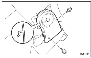
- Install the LH seat rear seat reclining cover with 2 screws.
15. INSTALL RH SEAT REAR SEAT RECLINING COVER
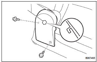
- Install the RH seat rear seat reclining cover with 2 screws.
 Disassembly
1. REMOVE RH SEAT REAR SEAT RECLINING COVER
Remove the 2 screws.
Remove the RH seat rear seat reclining cover by
pulling it out in the arrow mark direction shown in
the illus ...
 Installation
1. INSTALL REAR NO. 2 SEAT ASSEMBLY RH
Place the rear No. 2 seat assembly RH in the cabin.
NOTICE:
Be careful not to damage the body.
Install the seat with the bolt.
Torque: ...
Other materials:
Pressure Control Solenoid "C" Performance (Shift
Solenoid Valve SL3)
SYSTEM DESCRIPTION
The ECM uses signals from the vehicle speed sensor to detect the actual gear
position (1st, 2nd, 3rd, 4th
or 5th gear).
Then the ECM compares the actual gear with the shift schedule in the ECM memory
to detect mechanical
troubles of the shift solenoid valves and valve bo ...
Installation
1. INSTALL FRONT SHOULDER BELT ANCHOR
ADJUSTER ASSEMBLY
Install the front shoulder belt anchor adjuster
assembly with the bolt.
Torque: 42 N*m (430 kgf*cm, 31 ft.*lbf)
2. INSTALL CENTER PILLAR UPPER GARNISH
3. INSTALL FRONT SEAT OUTER BELT ASSEMBLY
NOTICE:
Do not disassemble ...
Indicator Circuit
DESCRIPTION
The indicator displays the location of the obstacle and the approximate
distance between the vehicle and
the obstacle either by blinking or turning on.
WIRING DIAGRAM
INSPECTION PROCEDURE
1 CHECK HARNESS AND CONNECTOR (CLEARANCE WARNING ECU - AIR CONDITIONER
AMPLIFIER)
...
